In Part 2 (Spring 2005 Issue 4), we covered how to specify the various devices required for interfacing and controlling the electrical equipment in an automated
control system.
In Part 3, we will cover the steps needed to design our automated control system. The design topics will include planning by defining our sequence of operation, creating a schematic with the devices shown in a high-voltage to low-voltage order, input to output design layout, panel layout, wiring diagrams, bill of materials, software tools to document our design, choices between using hard-wired relays versus a PLC with programming, etc.
As stated in the previous articles, special expertise is generally required to design, wire, install, and operate industrial automation control systems. Persons without such expertise or guidance should not attempt control systems, but should consider seeking the services of a qualified System Integrator. Control systems can fail and may result in situations that can cause serious injury to personnel or damage to equipment. The information provided in this series of articles is provided “as is” without
a guarantee.
Design 
The design for our control system will be in the form of a documenting task. The challenge will be to get our design specifics down on paper so that it can be easily understood. It is important that anyone can look at our documents in the future and be able to interpret the information. Useful to us at this step will be any notes and lists that were developed during the “Identifying” and “Specifying” phases of our automated control system.
Sequence of Operation
In most cases, the first step in designing our control system will be to define the process or actions to take place, by way of a “sequence of operations” description. The sequence should show or list each operational step in our process.
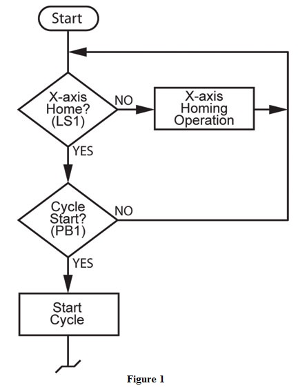
Our particular application may be better suited to using a flowchart that shows the sequence of operation by means of decision-making steps and actions that need to take place. Figure 1 shows a partial example of a flowchart.
A flowchart can be developed with graph paper and a pencil, or an application software program such as MicroSoft Visio®. MicroSoft’s Word software program has a built-in drawing tool that contains flowchart symbols.
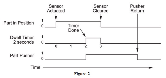
In some cases, the application may be better suited to using a timing chart, in which each condition and event is graphed in a time relationship to each other, as shown in Figure 2.
Once we have a sequence of operation developed and a list of our input and output devices, we can determine if our automated control system is best suited for hard-wired relay logic or can benefit from a PLC1. A PLC can be cost-effective when used in place of only a half dozen industrial relays and a couple electronic timers. It adds the flexibility of making future “logic” changes without the labor of making wiring changes.
Schematic
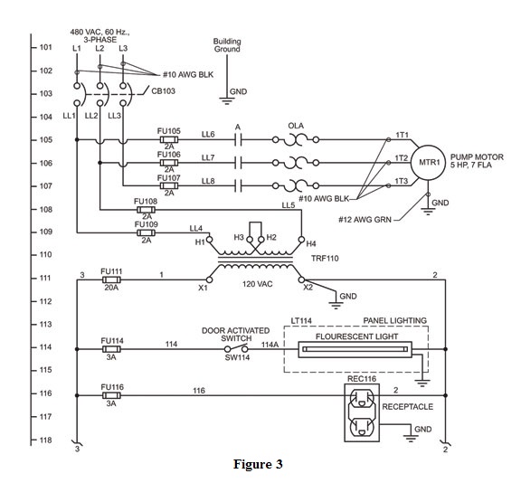
The next step in our design is to develop a schematic. Most electrical designers and engineers define a schematic as a drawing that shows the logical wiring of an automated control system. A control schematic is normally drawn in the form of a ladder, showing the various wiring conditions. This analogy of a ladder is what PLC ladder logic was based upon. It made the transition to PLC ladder logic easier for engineers and electricians because they were accustomed to trouble-shooting hard-wired relay control systems shown in a ladder fashion.
It is normal practice, as shown in Figure 3, to show input type devices on the left-hand side of drawings and output devices on the right-hand side. For example, the symbols for protective devices (fuses), contacts and overload relay elements are shown to the left, while the symbol for the motor is shown to the right.
The schematic should start with the incoming power, including protective devices such as circuit breakers and/or fuses. Our design should show the distribution of the AC power and include all circuitry and required devices for conformance to the National Electrical Code® (NEC®)2 and any local codes that might apply in our area.
It is normal practice to show any high-voltage devices, such as 3-phase motors, 480 or 240 VAC auxiliary equipment, etc. in this first section of the schematic. Next, we will show a control power transformer used to step the higher incoming voltage down to our system control voltage (115 VAC). Our control voltage can be something other than 115 VAC; for example, we could have a control voltage of 24 VDC, which is common for many electrical control devices. The control transformer needs to be sized (VA rating) based on our known or calculated “load” of devices that will be powered from the transformer in our automated control system.
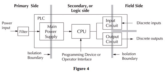
At this point in our schematic, we need to look at device wiring isolation strategies. PLCs provide ideal isolation because its circuitry is divided into three main regions separated by isolation boundaries as shown in Figure 4. The PLC’s main power supply includes a transformer that provides isolation, and the input and output circuits that use opto-couplers to provide additional isolation. When wiring a PLC, it is extremely important to avoid making external connections that connect logic side circuits to any other.
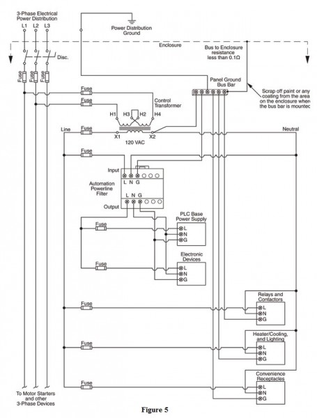
Electrical isolation provides safety, so that a fault in one area does not damage another. Using Figure 5 as reference, we see a transformer which provides magnetic isolation between its primary (high voltage) and secondary (control voltage) sides. A powerline filter provides isolation between the control power source and the electronic devices.
Figure 5 also shows some general suggestions for device grounding and distributing the control power to various devices, along with individually fusing these devices.
Proper grounding is one of the most important things in good automated control system design. The more details we can show on the schematic to reflect all points that need to be grounded, the better chance we have of a properly grounded control system that provides both safety and functionality.
Why is grounding important? Electronic instrumentation such as PLCs and field I/O are typically surrounded by various types of electronic devices and wires. These electronic devices may include power supplies, input/output signals from other instrumentation, and even devices that are near the instrumentation enclosure. All these may present a risk of Electromagnetic Interference (EMI) or transient interference. This type of interference may cause failure or erratic operation of the device.
We should consider using a second transformer to source AC power to DC power supplies. Input circuits should be utilized to isolate the output circuits and prevent voltage from the output transients (spikes) from being induced into the input circuits. In some cases, we may need to use a constant voltage transformer to stabilize the incoming AC power source supplying the PLC to minimize shutdowns due to power surges, voltage dips and brownouts. When using a constant voltage transformer to power a PLC, the sensors connected to the PLC inputs should use the same power source. Otherwise, the AC source voltage could drop low enough to cause inaccurate input data. Also, the use of an isolation transformer, for example 115 VAC primary to 115 VAC secondary, can provide additional suppression of EMI from other equipment. Isolation transformers should be used near equipment that produces excessive electrical noise.
If DC power is required in our control system, we need to calculate the worst case amperage draw (load) of all the devices that will be powered from the DC supply. We also need to look at the amount of “ripple” the devices being powered can tolerate and select a DC power supply that can meet the most stringent requirement. Ripple is the amplitude of the AC component that rides on the DC voltage signal. A typical rating for most applications involving DC powered sensors would be 100 mV peak-to-peak. It is also a good idea to double the calculated amperage capacity of the DC power supply. This is especially important if our control system needs to meet Underwriters’ Laboratories, Inc.® (UL)3 508A.
The next section of our schematic will show the hard-wired devices that are powered from our control voltage (115 VAC). If our control “logic” is based on hard-wired relays, this is where we would show the hard-wired connections, along with the normal 115 VAC powered devices, such as DC power supplies, 115 VAC power to PLC power supplies, auxiliary devices, etc. Figure 6 is a partial example of the hard-wired section of our schematic.

This is a good point to mention surge suppression. Surge suppression devices are an important component in achieving a reliable power distribution system. These devices protect the electronic components from sudden power surges that can cause considerable damage. Inductive load devices (devices with a coil) generate transient voltages when de-energized with a relay contact. When a relay contact is closed it “bounces,” which energizes and de-energizes the coil until the “bouncing” stops. The transient voltages generated are much larger in amplitude than the supply voltage, especially with a DC supply.
If using a PLC, the final section of our schematic will show the input and output modules. Figure 7 is an example of the wiring for an input module.
We would make use of reference line numbering and, in most cases, we would show all of the input modules first, then the output modules. If we have analog I/O, we would want to show the analog inputs, then the analog outputs, and finally our discrete inputs and outputs. Generally we would use one sheet of our schematic to show each module.
Panel Layout
Once we have our schematic finalized, the next step is a panel layout drawing. In most cases, the actual panel is referred to as a subpanel. We can mount all the components to a structure (the subpanel), wire all the components, and do this before mounting the subpanel in the control system enclosure. The panel layout drawing should be done to scale and include dimensions for the panel builder to follow when laying out the components. Special attention should be given to component location and spacing. We need to follow the manufacturer-recommended mounting distances and clearances. Figure 8 is a partial example of a panel layout drawing.
The higher voltage devices (those that operate at 240/480 VAC) should be mounted toward the top of the panel, keeping as much distance as possible between the high-voltage devices and any electronic devices, such as PLCs, DC power supplies, electronic timers, etc. Keeping the high-voltage devices toward the top allows us to cover all of the high-voltage devices with a non-conductive safety shield for personnel safety. It keeps the lower voltage devices grouped together, allowing access to wiring terminals that will aid in troubleshooting our control system. In some cases, a metal partition between the high-voltage section of our control panel and any sensitive electronic devices can act as a shield from any EMI generated by the high-voltage devices.
In our panel layout design, we need to include wire duct between the various components. The wire duct simplifies the wire routing between components, keeps the wires in place, makes working with the wires easier, and gives the panel a well-organized look. We should also make use of terminal blocks in our design. Terminal blocks can be sized, organized and even color-coded to handle the different types of signals that enter and leave our control panel. We may choose to use black for high voltage, red for inputs, violet for outputs, etc. We should try to locate the terminal blocks so they provide the best wire routing from the components to the terminal blocks. The terminal blocks also make it convenient for the electrician to terminate his field wiring when the control enclosure is installed.
Our design should include the selection of the enclosure that will house our control system. We need to consider the environment where the enclosure will be located. Outdoors? Indoors? Wash down required? Refer to the section on enclosures in Part 2 of this series of articles for references to NFPA’s National Electrical Code (NEC)2, the National Electrical Manufacturer’s Association (NEMA)4, OSHA5, and a list of items to consider when selecting an enclosure.
Bill of Materials
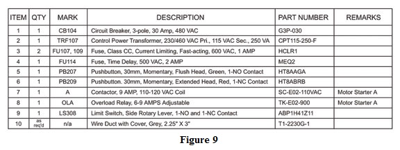
The Bill Of Materials (BOM) should list each component in our automated control system, the quantity of each component, any designations or “marks” that allow us to easily identify the component on our schematic, a description of the component, and its part number. We also have comments or remarks about the component that will help the panel builder know what needs to be done when the control panel is being built. Figure 9 is a short example of a bill of materials.
The BOM can be in the form of a table drawn on one of the sheets along with the schematic and panel layout. It can also be done as a spreadsheet, which would allow easy indexing and future referencing.
Wiring Diagram
A wiring diagram, sometimes referred to as an interconnecting diagram, is used mainly for installation by the electrician for routing and terminating the wiring between the various devices and enclosures in the control system. Figure 10 is a good example of a wiring diagram.
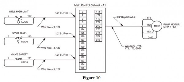
It should include all control enclosures or cabinets, any external devices that are wired into control enclosures, junction boxes, conduits, wireways, etc. The wiring diagram usually includes conduit sizes, distances, number of conductors between devices, wire sizes, colors, wire numbers, terminal blocks, etc. The wiring diagram is also useful for system startup and later for locating wire routing and devices during troubleshooting.
Design Tools
Although all of the tasks related to documenting the design can be performed with nothing more than a pencil, paper and a ruler, it is normally more efficient to use a software drafting utility, such as AutoDesk’s AutoCAD® or AutoCAD LT® software. The biggest advantage in using a software drafting program to create schematics, panel layouts, bill of materials and wiring diagrams is the ability to re-use the work for future electrical control system designs. The drafting software can also be used to create our sequence of operation, flowchart or timing diagram. Add-ins for the various drafting software packages are geared toward electrical control system design. These add-ins contain pre-constructed elements of different manufacturers’ electrical devices. This may include schematics of PLC I/O modules, power supplies, communication devices, etc. These pre-constructed elements also include scaled outlines of relays, motor starters, terminal blocks, etc. that can be dropped into your panel layout design. One such add-in package that works with AutoCAD and AutoCAD LT for electrical control design and includes some pre-constructed elements for various PLC manufacturers is ECT’s “promis•e draw” software. More information on the promis•e draw can be found at:
https://www.automationdirect.com/static/specs/pcdrawspecs.pdf. This software has the ability to act as a database for components that would be used in our control system design and can aid in coordinating the components between our schematic, panel layout and bill of materials.
Discussion of automation control systems will continue in our next issue with Part 4, Build, Install and Maintain.
By Tom Elavsky,
AutomationDirect
Footnotes:
1 For “Considerations for Choosing a PLC” refer to:
https://support.automationdirect.com/docs/worksheet_guidelines.html
2 The National Fire Protection Association® (NFPA®) produces the National Electrical Code® (NEC®), publication NFPA 70. Further information can be found at http://www.nfpa.org/ Another good reference from the NFPA is Electrical Standard Industrial Machinery, publication NFPA 79.
3 Information for the National Electrical Manufacturer’s Association (NEMA) can be found at http://www.nema.org. NEMA is also being harmonized with the International Electrotechnical Commission (IEC) (www.iec.ch/) and other European standards. Additional information can be found at the Global Engineering Documents’ Web site (www.global.ihs.com). Global Engineering Documents is also the source for obtaining NEMA, IEC and CE documents.
4 Additional information can be found on OHSA’s Web site: (http://www.osha.gov/SLTC/controlhazardo)
Originally Published: Sept. 1, 2005


