In Part 3 (Fall 2005 Issue 5), we covered how to design our automated control system and the importance of documenting the design. We discussed the various types of documents that would be typical for an automated control system design, why and how we would use these documents, and finally the tools that can be used to create the documents.
In Part 4, we will cover the steps needed to build, start up, and maintain our automated control system. The build section will include tips on the use of a subpanel, terminal blocks, grounding, shielded cable, etc. We will cover the steps to start up the system so that it is brought online in a safe and logical manner, and also give some suggestions for developing a plan to maintain the control system.
As stated in the previous articles, special expertise is generally required to design, wire, install, and operate industrial automation control systems. Persons without such expertise or guidance should not attempt control systems, but should consider seeking the services of a qualified System Integrator. Control systems can fail and may result in situations that can cause serious injury to personnel or damage to equipment. The information provided in this series of articles is provided “as is” without a guarantee of any kind.
Build:
During the design of our control panel, we pointed out the benefits of using a removable subpanel. In building the subpanel, it is best to secure the components from the front side. This will make it easier to replace any failed device or component in the future.
 We can also make installation and maintenance easier by using terminal blocks mounted to the subpanel that will connect to all external devices. This will allow the installing electrician to quickly dress and terminate the field wires. Another terminating method that has added benefits is to design our control panel with mating connectors so that the field wiring could be plugged into connectors mounted on the panel.
Wiring Recommendations
The following guidelines provide general information on how to wire most automation equipment. For specific information on wiring a particular PLC or device refer to the installation manual for that device or PLC.
• Each terminal connection can accept one 16 AWG ortwo 18 AWG size wires. Do not exceed this recommended capacity.
• Always use a continuous length of wire. Do not splice wires to attain a needed length.
• Use the shortest possible wire length.
• Use wire trays for routing where possible.
• Avoid running control wires near high energy wiring.
• Avoid running input wiring close to output wiring where possible.
• To minimize voltage drops when wires must run a long distance, consider using multiple wires for the return line.
• Avoid running DC wiring in close proximity to AC wiring where possible.
• Avoid creating sharp bends in the wires.
• Install a powerline filter to reduce power surges and EMI/RFI noise.
Important Wiring Safety Recommendations
Warning: Providing a safe operating environment for personnel and equipment is your responsibility and should be a primary goal during system planning and installation. Automation systems can fail and may result in situations that can cause serious injury to personnel or damage to equipment. Do not rely on the automation system alone to provide a safe operating environment. Use external electro-mechanical devices, such as relays or limit switches that are independent of the automation equipment, to provide protection for any part of the system that may cause personal injury or damage.
 Warning: Every automation application is different. Therefore, there may be special requirements for your particular application. Be sure to follow all National, State, and local government requirements for the proper installation and use of your equipment.
Plan for Safety
As we have stressed in previous articles, the best way to provide a safe operating environment is to make personnel and equipment safety part of the planning process. Examine every aspect of the system to determine which areas are critical to operator or machine safety.
If you are not familiar with system installation practices, or your company does not have established installation guidelines, you should obtain additional information from the following sources:
NEMA1: The National Electrical Manufacturers Association, located in Washington, D.C., publishes many different documents that discuss standards for industrial control systems. You can order these publications directly from NEMA. Some of these include:
• ICS 1: General Standards for Industrial Control and Systems
• ICS 3: Industrial Systems
• ICS 6: Enclosures for Industrial Control Systems
NEC2: The National Electrical Code provides regulations concerning the installation and use of various types of electrical equipment. Copies of the NEC Handbook can often be obtained from your local electrical equipment distributor or your local library.
Local and State Agencies: Many local governments and state governments have additional requirements above and beyond those described in the NEC Handbook. Check with your local Electrical Inspector or Fire Marshall office for information.
Grounding
Why is grounding important? Electronic instrumentation such as PLCs and field I/O are typically surrounded by various types of electronic devices and wires. These electronic devices may include power supplies, input/output signals from other instrumentation, and even devices that are near the instrumentation enclosure. All these may present a risk of Electromagnetic Interference (EMI) or transient interference. This type of interference may cause erratic operation of components and cause failures.
In addition to device interference, automation equipment and devices could be damaged by powerful line surges. These line surges may come from common voltage fluctuations from a power supply, lightning, or unintentional contact with a high voltage line. A power surge will cause a temporary failure, fuse burn-up, or even very serious damage to the equipment.
Grounding provides a low impedance path that limits these voltages and stabilizes interference. Grounding is a must to protect your automation equipment and devices from serious damage, failures, and even potential risk to users.
Grounding is the foundation of achieving a reliable power distribution system. During the panel and control system build, it is important that a reliable grounding system be implemented. Poor grounding or improper or defective wiring may be the cause of most problems affecting power quality. The following is a list of existing grounding standards that may be used for reference:
• IEEE Green Book (Standard 142)
• IEEE Emerald Book (Standard 1100)
• UL96A, Installation Requirements for Lightning Protection Systems
• IAEA 1996 (International Association of Electrical Inspectors) Soars Book on Grounding
• EC&M – Practical Guide to Quality Power for Electronic Equipment
• Military Handbook – Grounding Bonding and Shielding of Electronic Equipment
Once all the important considerations mentioned above have been determined, the mounting, bonding, and grounding of the chassis may be started. The following list provides a brief explanation of each of these terms:
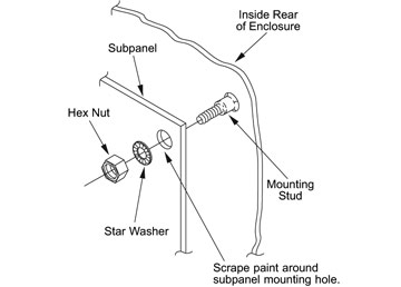
• Mounting: refers to the actual physical installation of each device, instrument or component to either the subpanel or other connected equipment.
• Bonding: refers to the joining of metallic parts of a chassis such as; frames, shields, assemblies and enclosures. Joining or bonding these components properly reduces the interference from EMI and ground noise.
• Grounding: refers to a connection to a grounding conductor to provide overload and interference protection.
As mentioned before, grounding protects the instrumentation, devices, or components from power surges and reduces the effect of EMI and ground noise. Figure 1 (above) shows a typical method for grounding the subpanel to the enclosure cabinet to assure proper grounding.
 Note: Please remember that bonding and grounding are important safety requirements that are mandatory by local codes and regulations. The installer must verify the local codes to determine what grounding and bonding methods are permitted. Always make sure that power supplies are properly grounded to ensure elimination of electronic noise interference.
 Note: When using ground lugs and installing more than one on the same stud, make sure to install the first lug between two star washers and tie it with a nut. Install the second lug over the nut of the first lug followed by a star washer and another tightened nut.
Shielded Cables
A shielded cable is an insulated cable consisting of strands of copper or other material enclosed with a metallic shield underneath a jacketed sheath. Shielded cables are used to reduce the interference from electrical noise.
Some instrumentation requires the use of shielded cables for specific connections. When installing instrumentation, verify whether any connection requires a shielded cable. Failure to use the shielded cable will result in erratic readings or signals from the instrumentation. If the product being installed requires shielded cables, the grounding specifications provided by the manufacturer manual must be followed. Improper installation of shielded cables may cause a ground loop that will cause failure on a processor or would allow noise into the logic circuit.
There are various types of shielded cable available for different uses. The shielded cables listed below are the most commonly used for automation control systems and instrumentation:
• Foil Shield: These cables consist of aluminum foil laminated to a polyester or polypropylene film. The film provides mechanical strength and additional insulation. The foil shield provides 100% cable coverage for electrostatic shielded protection. Foil shields are normally used for protection against capacitive (electric field) coupling where shielded coverage is more important than low DC resistance.
• Braided Shield: These cables consist of groups of tinned, bare copper, or aluminum strands. One set is woven in a clockwise direction, then interwoven with another set in a counter-clockwise direction. Braided shields provide superior performance against diffusion coupling, where low DC resistance is important, and to a lesser extent, capacitive and inductive coupling.
• Spiral Shield: The spiral shield consists of wire (usually copper) wrapped in a spiral around the inner cable core. The spiral shield is used for functional shielding against diffusion and capacitive coupling at audio
frequencies only.
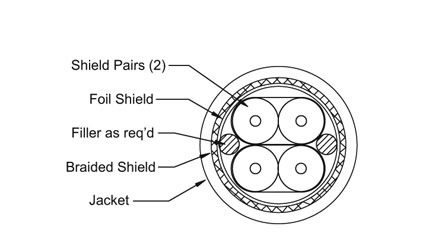
• Combination Shield: These cables consist of more than one layer of shielding. The combination shield is used to shield against high frequency radiated emissions
coupling and electrostatic discharge (ESD.) It combines the low resistance of braid with 100% coverage of foil shields and is one of the more commonly used types of shielded cable in today’s industry.
Figure 2 (to the right) shows a typical cross sectional area of a shielded cable that makes use of combination shields.
Mounting of Electronic Instrumentation
Electronic instrumentation is typically installed inside an enclosure with other devices. Therefore, the installation of the instrumentation must take into consideration that the panel layout accommodates all the necessary components. In addition to the panel layout, the following specifications should be considered:
Electronic instrumentation can be affected by interference from other electronic devices or EMI. This interference causes static that may interrupt communications or signals from other devices. Use these guidelines to prevent any possibility of interference with your equipment:
• Environmental specifications that cover the operating temperature, humidity, vibration, noise immunity, etc.
• Power requirements are specific to each piece of equipment. When installing instrumentation always make sure to follow the manufacturer’s power requirement guidelines for your specific piece of equipment.
• Use components with Agency Approvals such as UL, CE, etc.
• Make enclosure selections based on component dimensions, recommended mounting clearances, heat dissipation and EMI.
If installing a PLC base or chassis which consists mainly of mounting, bonding, and grounding, it is very critical to the proper operation of the PLC and its related devices and components to closely follow the manufacture’s recommendations. There are many cases of a PLC experiencing “noise” problems, when the problem is found to be that the base wasn’t grounded to the subpanel.
I/O Testing
The last item to consider at the completion of building your control system is to do a complete I/O checkout. This will assure that the point-to-point wiring between the I/O module terminals and the field wiring terminal blocks has been done correctly.
To start, create a list with each I/O point shown and include any details of what criteria is being tested. It is also helpful to include a check box that can be used to check off each point after it is tested. Normally this list can be created from an I/O list or tag name list that was created when designing your PLC ladder logic or HMI operator interface.
Include the test criteria for each point on the list. As an example, discrete input and output points would be listed as normally “off” and then checked for their “on” state. Analog points, both input and output, could be checked at different values. For example, if using a current input module, you may want to simulate 4 mA (low value), 12 mA (middle value) and 20 mA (high value).
The actual testing normally requires a two-person team. One person uses a PC connected to the PLC to view the status of each point tested and to simulate outputs, and the other person physically applies a signal to inputs and monitors outputs with the use of an indicator on discrete outputs and a meter on analog outputs.
Start Up:
 The startup of our automated control system begins once we have installed our control system enclosure and auxiliary equipment, terminated all field wiring, and completed required testing. This process is also called “commissioning” the automated control system and related equipment/process.
As a starting point, it is best to isolate the various sections of our control system power wiring by removing the fuses and/or opening circuit breakers. The best tool to use during commissioning is the schematic diagrams. We will want to start at the incoming power, and basically work our way through the entire schematic.
As a first step, we may want to apply power to the main circuit breaker or fused disconnect of our control system. Then, measure the voltage for proper values, phase-to -phase and each phase-to-ground, if the incoming power is three phase. Next, we can turn on the main circuit protector and check the voltage at each device that is fed from the main source. Then start turning the circuit breakers on or replace the fuses one circuit at a time and make additional voltage checks and test equipment operation that may be powered from
the circuit.
Keep in mind that every control system will not be the same. Therefore, each system will require a different strategy to bring the equipment online safely. Consider having motors uncoupled from their respective loads, air pressure off, disabling hydraulics, and using Lockout/Tagout (LOTO) procedures. Measure voltages as you go. If using a PLC, connect a PC to it and monitor the ladder logic to make sure conditions, states, etc. are responding correctly.
Maintain:
It is important to develop a routine maintenance schedule for your automated control system. Having a routine schedule for checking critical components and devices in the system will increase the longevity of the system and more importantly, it will help eliminate future problems. Set up the schedule based on a monthly or quarterly time period, depending on the item to be done. The following are some of the items you may want to consider in your maintenance schedule:

• Check and record voltages at various circuits
• Tighten all connections (with power removed)
• Check backup batteries, and/or replace on a routine schedule
• Check indicators and perform lamp tests
• Visually inspect for loose or frayed wiring, moisture in enclosure, etc.
• Check to make sure plug-in connectors are tight and secured
• Test all alarm systems, horns, sirens, etc.
• Check and record any configuration settings
• Perform and record calibrations
• Check all I/O points on a yearly basis
• Check and record power usage
• Check equipment run times for determining
maintenance or replacement
• Measure device current to set a benchmark and
compare for changes
• Review any diagnostic history, including events and alarms
• Check diagnostics that may be programmed into the HMI operator interface
This wraps up the series of articles on automated control system specification, design and installation. We hope you have found this information useful. Look for a downloadable complete guide, with additional details, on our technical web site sometime in the near future.
By Tom Elavsky,
AutomationDirect
Footnotes:
1 Information for the National Electrical Manufacturer’s Association (NEMA) can be found at their Web site at: http://www.nema.org. NEMA is also being harmonized with the International Electrotechnical Commission (IEC) (Web site: www.iec.ch/) and other European standards. Additional information can be found at Global Engineering Documents’ Web site at:www.global.ihs.com. Global Engineering Documents is also the source for obtaining NEMA, IEC and CE documents.
2 The National Fire Protection Association (NFPA) produces the National Electrical Code (NEC), publication NFPA 70. Further information can be found at their Web site athttp://www.nfpa.org/. Another good reference from the NFPA is Electrical Standard Industrial Machinery, publication NFPA 79.
Originally Published: March 1, 2006

