For their undergraduate senior capstone project, a team of Mechanical Engineering students at Portland State University (PSU) recently designed an electronic system upgrade for the control system of a 100-year-old beam testing machine. Using a range of AutomationDirect parts, the purpose of the project was to make the operator experience comparable to modern machines.
The project was proposed and guided by PSU Mechanical and Materials Engineering (MME) staff William Wood, Professor, Robert Turpin technical and fabrication specialist, & Tae Kyu Lee, Associate Professor. The project team, led by Thomas Langston, included fellow students Giovanni Castillo-Martinez, Moonsu Park, Hassan Alherz, Ian Winter, Thanh Truong, Jaime Meza-Martinez, & Ben Vorobets.
During the summer of 2015, a Riehle Beam Testing machine was donated by the City of Portland Materials Field Testing Laboratory to PSU to support the university’s MME research and education. PSU’s office of Graduate Research then relocated the system to PSU’s Materials Research High-Bay lab located in the Oregon Museum of Science and Industry’s (OMSI) PEPCO building.
Manufactured in 1916 by the Riehle Brothers Company in Philadelphia, Pennsylvania, the beam tester is a triple-beam balance load scale with an electric motor-driven lead screw-type force applicator capable of compression, tension and three-point bending tests with a load capacity of 150,000 lbs.
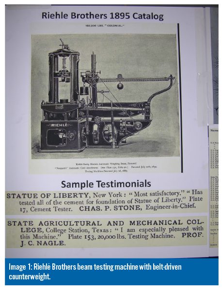
Since the scale mechanism is a large version of a classic triple-beam balance lab scale used in classrooms, laboratories and manufacturing facilities, the machine requires the operator to move the counterweight out on the balance beam to keep the increasing load in equilibrium. A Riehle Brothers design to automate this process is shown (Image 1) using a belt driven counterweight. It uses an electric motor driven by a signal from an analog position sensor, likely a type of potentiometer, located at the end of the beam.
Most beam testing machines from this era have been replaced with modern systems utilizing electronic controls, load cells and complex servo hydraulic loading mechanisms. These systems offer greater speed, modularity and ergonomics for the operator over the lead screw designs of the past.
The modernization project accomplished the same function using AutomationDirect’s Productivity® 2000 PLC control, a direct-drive servo motor at the counterweight crank wheel, and a non-contact laser displacement sensor at the end of the beam. The Productivity2000 PLC is used to process the position signals and output the desired motion parameters to keep the beam balanced and machine forces in equilibrium.
A new motor and VFD controller were chosen to replace the existing motor. The VFD allows continuously variable feed rates of the crosshead. The original machine had a limited number of discrete feed rates available through the transmission, and tests were run at a single speed. A VFD motor combination allows for both lower and higher speed operation without loss of torque needed for a given test. Additionally a low RPM motor was sourced to provide even lower feed rates which are desirable for certain tests. Mounts were designed to install the direct-drive motor.
Auto-Balancing Mechanism
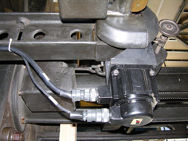
A SureServo servo system from AutomationDirect was used to maintain balance of the beam. The system takes a direct position input from a Wenglor photoelectric laser distance sensor at the end of the balance beam to create a set point for the PID controller integrated into the amplifier and controller system. The servo motor is directly coupled to the shaft of the counterbalance drive crank. This allows the servo to move the counterweight to keep it balanced. (Image 2)
The Riehle machine may be old, however there is nothing deficient about the testing method that it employs, and using the modern equipment listed above, the results the machine provides are comparable to the continuous stress/strain data produced by a modern machine.
In addition to being a student educational project, and a testing platform for the PSU MME Department, the retrofitted Riehle testing system was presented at the 2016 OMSI Maker Faire. This annual event attracts many specialists and interest groups in the area of design, engineering, manufacturing and materials. This event was timely in that it occurred during the machine’s 100th anniversary and provided an opportunity to publicly highlight the history of metallurgical study and its current state of development.
 Mechanical Description
The Riehle’s triple-beam balance mechanism functions similarly to a laboratory balance scale except that it uses two additional lever mechanisms over a single one. The machine will be described in three parts: the loading assembly, the drive train and the balance beams system.
Loading Assembly
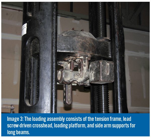
Capable of tension, compression and bending tests, force is applied to the loading assembly by the crosshead driven by two vertical lead screws (Image 3). The loading frame pivots on the larger balance beams that connect to the intermediate and scaled balance beams. Multiple attachment heads allow for multiple types of specimens to be loaded and tested. The loading assembly consists of the following parts: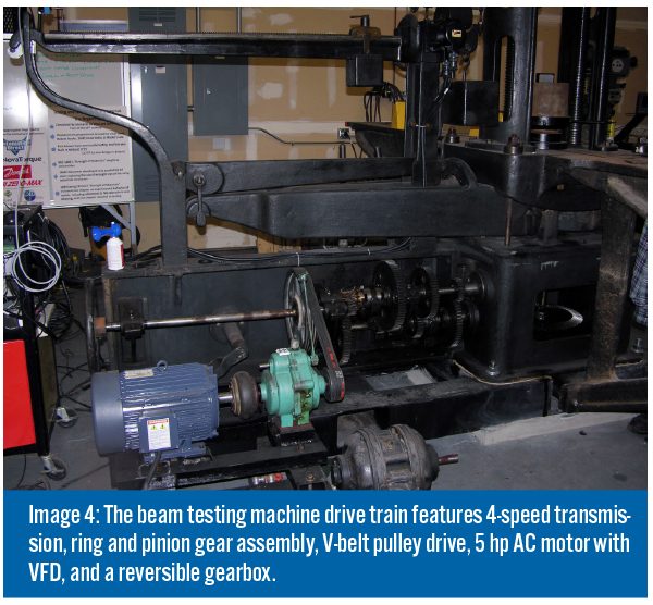
- Tension test frame
- Lead screw driven crosshead
- Loading platform
- Side arm supports for long beams
Drive Train
The drive train (Image 4) powers the lead screws and consists of the following:
- Ring and pinion gear assembly
- 4 speed transmission
- V-belt pulley drive
- Forward reverse gearbox
- 5 hp AC motor w/VFD
Balance Mechanism
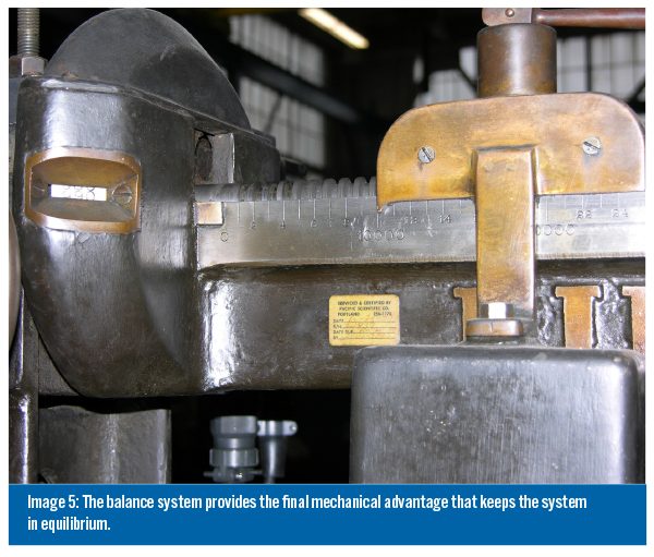
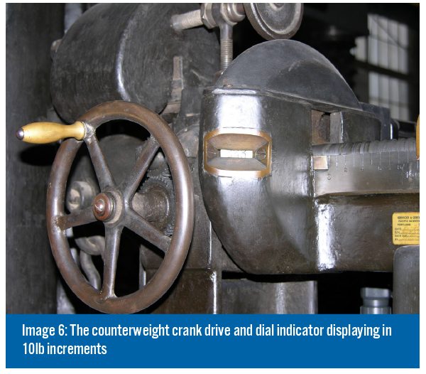
The balance system, consisting of the counter balance on the balance beam (Image 5) and the counterweight crank drive and the dial indicator showing 10lb increments (Image 6), provides the final mechanical advantage that keeps the system in equilibrium.
In addition to the electronic control system upgrades the team had to design and manufacture a steel support undercarriage to support and anchor the Riehle machine to the floor. They also identified the following five objectives for the control system retrofit:
- 1. Load calibration of the 150,000lb capacity bending and axial load frame
- 2. Upgrade the AC motor to an AC motor with Variable Frequency Drive (VFD) for improved speed control
- 3. Design and implementation of an auto load balancing operation, using an AutomationDirect supplied SureServo servo system
- 4. Re-installation and operation of the Riehle in its original operating condition with its gear driven applied load mechanisms highlighted and visible for OMSI museum visitors to demonstrate how structural materials properties were obtained 100 years ago.
- 5. Design and implementation of a control and data acquisition system using an AutomationDirect PLC to control the machine AND acquire, display, store, and post process load, crosshead displacement and strain outputs from system mounted sensors.
Conclusion
Installation of the major design components was completed in time for the 2016 Maker Faire event. During the event, a 4” x 6” x 12’ beam was loaded to 5,000 lbs showing visitors the deflection at which this load and beam span.
Both makers and event visitors alike were intrigued by the machine and fascinated by the tremendous mechanical advantage the drive-train applied to the beam using only a 5hp VFD motor.
 Engineers and advanced makers recognized the parallel between the original automated design and the current system as well as the advantages provided by modern PLC equipment. Particularly useful in this application, the Productivity 2000 provided a control hub for multiple digital I/O communications to separate components of the system. From this PLC, control of the balance mechanism is managed, but also integrated control of the VFD motor and data acquisition systems are made possible making the P2000 the primary test control module for the 2016 upgraded Riehle System.
Given the short amount of time for project completion, the engineering team accomplished an ambitious set of goals. The project surpassed all course requirements with excellent review ratings and all students received passing grades. The success of the project was made possible by the collaborative support from AutomationDirect, the stellar assistance from their Productivity2000 technical support team, and the advanced technical capability of AutomationDirect-supplied products.
By Thomas Langston,
PSU Mechanical Engineering Bachelor of Science pursuing MS in Materials Science
To learn more about programmable control, click here.
Originally Published: March 1, 2017