In Understanding Ladder Logic we touched on the origins of Ladder Logic, its structure and execution. So now that we have a understanding of what Ladder Logic is, we can dig a little deeper into how ladder instructions work. And to do that, we need to first understand Boolean math and logic gates. Now, this blog is not intended to be a Digital Systems class so put away your Karnaugh maps, you won’t need them. Instead, we’ll just look at a few logic gates and how they work.
The two logic gates that you will see represented most often in Ladder Logic are the AND and OR gates. As the truth tables below show, the AND gate needs all inputs (A and B) to be true before the output becomes true, whereas the OR gate needs just one input (A or B) to be true to make the output true. These truth tables can be duplicated with relay contact logic by connecting normally open contacts in series (AND gate) or parallel (OR gate) as seen below.
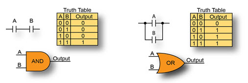
To equate this to a control circuit, let’s say Input A and Input B (often referred to as permissive bits) are the Door Open and Motion Detected inputs of a home alarm system. When wired in series, as with the AND gate, both conditions will have to be met before the alarm is activated. The door will have to be opened and the motion detector tripped before the alarm is triggered. With the OR gate, the inputs are wired in parallel and only one of the conditions is needed. In this case, the door opening or the motion detection will trigger the alarm. The option you choose is dependent on your application and on how the system is expected to perform. Pretty simple, right? And in its very basic form, that’s what Ladder Logic is. It’s the arrangement of permissive bits or contacts into a Boolean expression that determines whether an output should be ON or OFF.
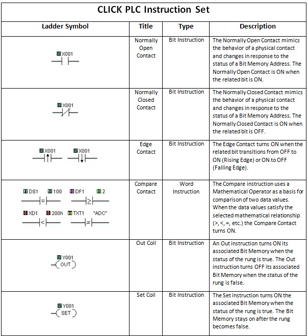
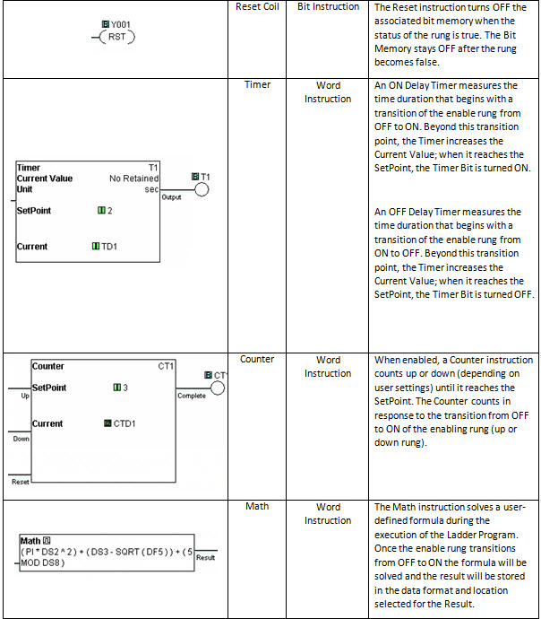
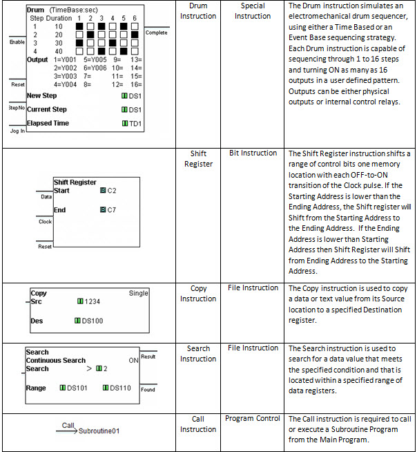
Today’s Ladder Logic programming has advanced to include more than just simple contacts and coils but the same underlying principle holds true. The true or false state of each input element in a rung and how it is connected will determine the output’s state. So let’s take a look at some of the instructions available in current PLCs. And for that we will use the CLICK PLC since it has a simple, easy-to-use instruction set. The table below contains all of the available Ladder Logic elements in the CLICK programming software with descriptions of their functions.
CLICK PLC Ladder Logic Instruction Set
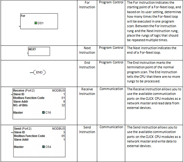
Click on image to view lager or click here.
As you can see, there are many more options available than just normally open contacts and many function blocks have been incorporated into Ladder Logic. For instance, the Drum and communication instructions are blocks of code that are stored and available for you to configure and use in your program. Now, we aren’t going to discuss every instruction available but one of the more frequently used instructions is the Compare contact.
The Compare contact can be programmed to look at two different numerical values; either or both values can be a variable or fixed value. The Compare instruction will evaluate if the two values are:
- Equal
- Not Equal
- One Greater Than the other
- One Greater Than or Equal To the other
- One Less Than the other
- One Less Than or Equal To the other
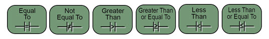
If the evaluation condition is met, then the result will be true, passing the logic path along to the next instruction or turning the rung output ON.
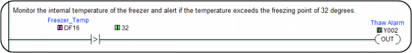
So, how can we use the Compare contact in an application? Imagine having a freezer full of frozen fish. The key word there is frozen! We don’t want to risk a smelly disaster if the fish were to thaw, so we’ve installed a sensor inside the freezer to monitor the temperature. The temperature sensor’s output produces an analog signal that is wired into a PLC. The PLC is programmed to take the analog signal and convert it into degrees Fahrenheit. If the temperature reads greater than 32 degrees, we can sound an alarm horn to alert us that the frozen fish will soon thaw and spoil.
Using the Compare contact instruction dialog box, as seen below, we can compare our actual Freezer Temperature (stored in memory location DF16) to the constant 32, which represents 32 degrees Fahrenheit.
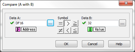
The Compare contact dialog box allows us to select any of the six different comparison methods. For this example, we have selected Greater Than so that if our Freezer Temperature ever becomes Greater Than the number 32, our Compare contact will become true.
An Out coil is then programmed from our Compare contact, as seen below, and will provide the signal that is wired to the external Alarm Horn, which alerts us to a problem with our freezer and hopefully giving us time to avoid disaster.
Ladder Logic is the most widely used programming language in industrial automation today. Its ease of use, traceability, and visual representation of physical components make it the favored programming method of many engineers. If you are new to PLC programming and would like to try Ladder Logic for yourself, download any of our programming software packages mentioned below for free and see what you think. After all, experience is the best teacher.