Directional air control valves are the building blocks of pneumatic control. Pneumatic circuit symbols representing these valves provide detailed information about the valve they represent. Symbols show the methods of actuation, the number of positions, the flow paths and the number of ports. Here is a brief breakdown of how to read a symbol.
Pneumatic Circuit Valve Symbols
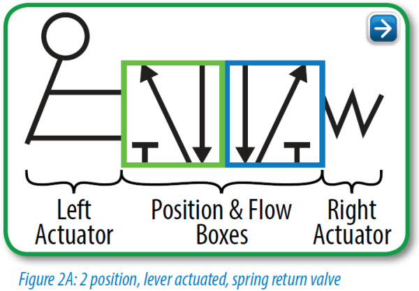
Most valve symbols have three parts (see Figure 2A below). The Actuators are the mechanisms which cause the valve to shift from one position to another. The Position and Flow Boxes indicate how the valve functions. Every valve has at least two positions and each position has one or more flow paths, thus every valve symbol has at least two Flow Boxes to describe those paths. Check out our Interactive Pneumatic Circuit Symbols here.
Position and Flow Boxes
The number of ‘position and flow boxes’ that make up a valve symbol indicate the number of valve positions. Flow direction is indicated by the arrows in each box. These arrows represent the flow paths the valve provides when it is in each position.
The Flow Box next to the ‘active’ actuator always shows the current flow path(s) of the valve. In the example above, when the lever is NOT being activated, the spring return actuator (right side) is controlling the valve, and the box adjacent to the spring shows the flow path. When the lever IS actuated, the box next to the lever shows the flow path of the valve. A valve can only be in one position at a given time.
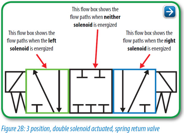
In Figure 2B (a 3-position valve), the valve has both solenoids and ‘spring return’ actuators on both sides, the spring return actuators will return the valve to the center position but only IF neither of the solenoids is active:
With this 3-position valve, the center flow box shows the flow path when neither actuator is active and the springs are holding the valve in the center position. In this fairly common example, the center box indicates that there will be no air flow (and the associated cylinder won’t move) unless one of the two actuators is active. This type of valve can thus be used to “bump” or “inch” a cylinder incrementally along its extension or retraction stroke for various purposes.
 Ports
Ports
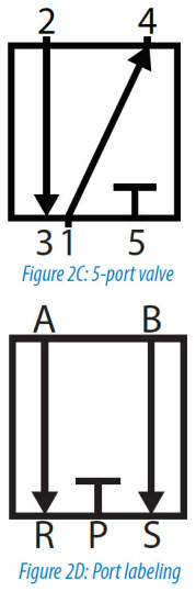
The number of ports is shown by the number of end points in a given box. Count only the ports in one flow box per symbol (For example there are three boxes in the Figure 2B valve symbol showing each of the three different positions possible for the valve). In Figure 2C, there are a total of 5 ports. Sometimes a port (usually an exhaust port) goes directly to atmosphere and there is no mechanical means for attachment of silencers, flow control valves, or any other accessories. To indicate this (in some flow diagrams), ports with attachment capability will have a short line extending beyond the box (as shown on ports 1, 2, & 4), while the ports you cannot attach to will not have the external line segment (ports 3 & 5 in this example).
Port Labeling
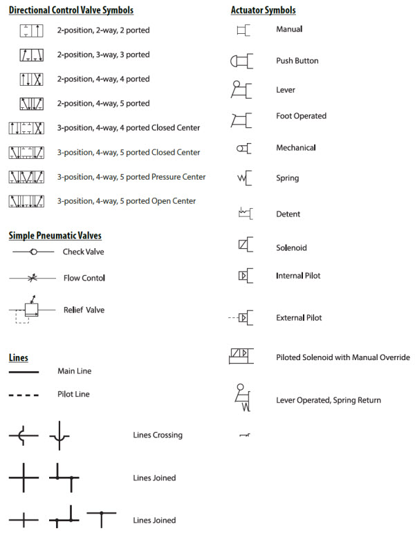
Port labels are typically shown on a single flow box per symbol. Different manufacturers label valve ports with different letters, but the labels at right are fairly standard. “P” represents the pressure inlet port, “A” and “B” are outlets (generally plumbed to the ‘extend’ and ‘retract’ ports on a cylinder), and “R” and “S” indicate the exhaust ports.
Ports vs “Ways”
Valves are often referred to by their number of ports, and also by the number of “ways” that air can enter or exit the valve. In most situations the number of ports and ways are the same for a given valve, but take a look at Figure 2C above.
It has five ports, but it is considered a 4-way valve because two of the ports share the same exhaust function. This is a holdover from hydraulics – where the two exhaust paths are joined (internally to the valve), so that only one return port is required, and only one return line is required to get the hydraulic oil back to the storage tank for re-use. In other words, in a pneumatic system the two exhaust ports (R and S in Figure 2D) are only counted as a single “way” since they both connect the valve to the same place (atmosphere). In the case of our pneumatic valve with similar functionality, the separate exhaust ports are created for mechanical simplicity (and as a cost saving measure), but they are not considered distinct “ways”.
The symbols on the next page detail many of the ports, ways, and positions of common pneumatic valves. The specification for “ways” can be somewhat tricky; analyzing the circuit symbols is a better method for verifying that a given valve offers the required functionality.
Common Valve and Actuator Symbols
Other Pneumatic Circuit Symbols
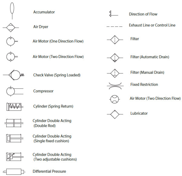
Other pneumatic components also have schematics or symbols, but these generally do not require as much explanation as those for the valves. Here are symbols for other commonly used pneumatic devices: Check out our Interactive Pneumatic Circuit Symbols here.
Originally published: March 21, 2016