Pneumatic systems as a whole can be simple, but this simplicity can be deceptive when it comes to selecting components. For instance, there are thousands of types, sizes, and variations of cylinders and valves, from off-the-shelf versions to custom designs. The sheer number of choices can be overwhelming, especially when options such as sensors are added to the mix. So how do you know what is right for your application? Since every application is different, that’s a hard one to answer. But the following section discusses a few considerations that can be helpful when selecting the right components for your pneumatic system. And taking the time to choose the right components for the job will ensure good performance, lower expenses, improve cycle rates, and prolong equipment life. Read on to learn more about your pneumatic system design!
Compressed Air Supply
Adequate sizing of compressors and feed lines is the first place to start to ensure proper system operation. Consistent plant air pressure with suitable flow allows pneumatic devices to operate as designed, as low or varying air pressure can negatively impact the final product and overall machine sequence. For example, a manufacturing plant was experiencing low air pressure in its facility at the end of the day shift, causing one of the machines to fault due to low air pressure in its pneumatic actuation system. The problem was found to be high-volume air consumers nearby, namely blow guns being used to clean machines at the end of each day. Insufficient capacity at the air compressor, or undersized plant air supply tubing and piping is a common issue and one to look out for. If air consumption is a major concern for your factory, check out our Interactive Air Consumption Calculator here.
Air Flow Control
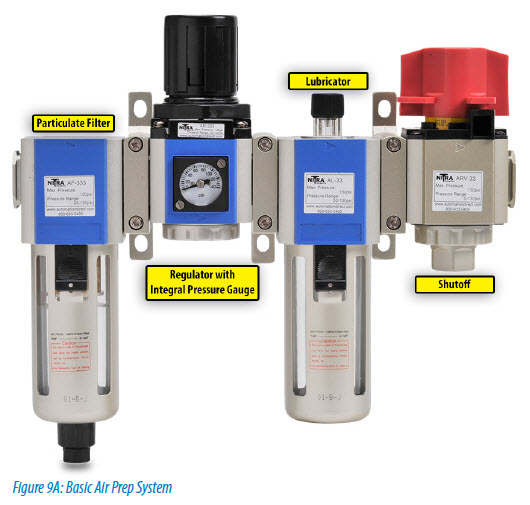
Once consistent and correct pneumatic system air pressure and flow is established, plant supply air should be connected to a manual, lockable air dump valve at each use point. This lockout, tag-out capability is important for isolating a machine—or a module of a large machine—for changeover, maintenance or tooling changes. A filter regulator should also be installed at the air dump valve. The filter removes dust particles and water that can cause wear and operation problems for pneumatic system components. A regulator is required to throttle to the design air pressure at the use point, typically 60 to 90 psi, as the plant air supply is usually higher, about 100 to 130 psi. Operating at the design pressure as opposed to plant pressure will reduce wear on pneumatic components.
An electric soft start valve downstream of the regulator allows air pressure to gradually increase at start-up, preventing sudden banging or slamming of cylinders at power up. This is especially important if 4-way, 2-position valves are used because a 2-position valve spool maintains its position after power off and the removal of air. When power and air is reapplied, air will return to the cylinder. If all air was exhausted, no air is available on the other side of the cylinder. This makes speed control with flow controls non-functional. The uncontrolled speed of the cylinder could cause a high-speed stroke, commonly ending with a bang. When soft start valves are correctly applied, a machine will typically return to its home position slowly and smoothly at power up.
Lubricators should be used sparingly and only when necessary. Most modern pneumatic components come lubricated from the factory and do not need oil. However, pneumatic motors on air tools and other equipment do require a lubricator and one should be supplied in these instances.
Cylinder Types
Pneumatic cylinders are a popular way to clamp, position and transfer parts in automated equipment and although there are many types of cylinders, their construction is fairly similar from one to another. Take a moment and review the Pneumatic Cylinders article to get a basic understanding of what cylinders are and how they operate. Understanding the basics helps to know how different applications affect the cylinder and piston rod.
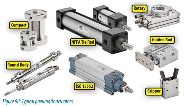
The first step in choosing a cylinder is deciding whether to use the single- or double-acting version. As mentioned previously, single-acting cylinders use compressed air to move the load in one direction and double-acting cylinders use compressed air for movement in both directions. With single-acting cylinders, air is supplied to only one side of the piston and a spring (or, in some cases, gravity) returns the piston to its original position once air pressure is removed. And while double-acting cylinders use more air (both for the extend and retract), they are well suited for loads that require both pushing and pulling.
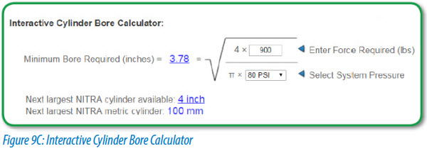
In both cases, force calculations can get complicated. In single-acting cylinders with a spring, the spring force opposing the push or pull increases as the stroke progresses. And in double-acting cylinders, push and pull forces are not equal, as rod area must be accounted for in force calculations. Often, manufacturers’ catalogs will list push and pull values for both double-acting and single-acting cylinders, with and without springs, in order to simplify these calculations and help with selecting the proper cylinder type. Take a look at our Interactive Cylinder Bore Calculator here.
Cylinder Sizing
The load is the primary consideration when determining cylinder type and piston size. The piston area (force factor) multiplied by the air pressure in the cylinder gives the available force. A general rule is to select a force factor that will produce a force 25% greater than the load to help compensate for friction and losses. Pneumatic systems are quite forgiving in terms of oversizing, but using components that are too big adds unnecessary expenses in terms of both purchase price and energy consumption.
The bore size (force factor) determines force at a given pressure. The operating pressure, which in a plant can typically range from 10 to 150 psi, is the first consideration when selecting a bore size. The next step in choosing the bore size is the amount of force that the application requires. Suppliers often provide charts to assist with calculating bore size. If the bore diameter is between sizes, fluid-power experts recommend rounding up to the next size. It’s also important to remember the bore diameter squares the thrust delivered. For example, a two-inch diameter cylinder has four times the power of a one-inch diameter unit. Therefore, doubling the bore quadruples the thrust.
In addition to load, designers must also take into account the speed at which the load will move. When compressed air flows through a system, there are pressure losses due to friction against the tube wall, flow around bends, and restrictions in valves and fittings (to name a few issues). Higher speeds result in greater pressure loss as the air must flow faster through the valves, tubing and ports. Attaining higher speeds also requires that the cylinder deliver more force in a shorter amount of time. A force that exceeds the load by 50% or more may be required to reliably move a load at high speeds. For example, a typical air compressor might supply air to a system at 100 psi. In an application with a slow-moving load, the actual pressure available at the piston might be reduced to no less than 90 psi. With that same load moving at a much faster rate, the available pressure could drop as low as 70 psi.
Pressure losses can be remedied by increasing pressure, but this must be done with caution: Too much pressure creates stress on the cylinder and could possibly damage the cylinder, as well as the load. In these instances, it’s better to go with a larger cylinder. Also keep in mind that raising system pressure means the compressor must work harder, increasing energy consumption of the overall pneumatic system.
Cylinder Accessories
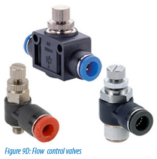 Even when a cylinder is sized properly, it may stroke too fast and require use of a flow control, typically by controlling flow of air leaving the cylinder. This also reduces noise problems caused by cylinders banging and reduces rapid exhaust racket. These flow controls are typically mounted directly to the cylinder, but can also be mounted inline near the cylinder, or at the valve if the hose between the valve and cylinder is less than about 3 feet.
Specifying cylinders with built-in cushions can help provide long-term performance in high-speed pneumatic motion applications. The cushions allow a cylinder to stroke at high speed and only slow down near the end of stroke for a quiet, low-impact stop. Adjustable pneumatic cushions are often the best solution, comprised of specially designed end caps with built-in flow controls. Mufflers can also be used to quiet cylinder or valve exhaust noise, and they are often a simple and low cost solution.
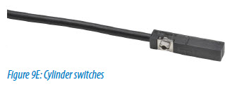
Cylinder position switches are extremely helpful in sequencing operations and prevent starting the stroke of one cylinder before the previous cylinder’s stroke is complete. Using timers to control a sequence instead of position sensors should be avoided in this and most cases. One stuck or slow cylinder during an automated sequence can cause a machine crash, costing much more than the cost of buying, installing and programming end-of-stroke sensors.
These are just a few of the many items to consider when designing a successful pneumatic system. Other factors, such as energy efficiency, can affect overall system design as well. But regardless of the design, watch out for the common issues and always be sure to supply, prep and distribute the air properly. When properly applied, your pneumatic devices and actuators will have a long life with limited operational issues along the way, and with minimal required maintenance.
These are just a few of the many items to consider when designing a successful pneumatic system. Other factors, such as energy efficiency, can affect overall system design as well. But regardless of the design, watch out for the common issues and always be sure to supply, prep and distribute the air properly. When properly applied, your pneumatic devices and actuators will have a long life with limited operational issues along the way, and with minimal required maintenance.
Control Valves
Once the cylinders are selected, you should now have a good idea of the flow rate and pressure of compressed air needed. With this information, you can select control valves. Items to consider in valve selection are size (flow capacity), type and actuation method.
 Valve Type
Choosing the right type of valve for the job required is not as difficult as it may seem. For cylinder control, the simplest method is to use a 3-way valve for a single-acting cylinder and a 4-way valve for a double-acting cylinder. Systems can be much more complex if needed, but let’s focus on a basic system for now. The form factor of the valve can vary a great deal and many people have a variety of preferences. It’s usually best to make sure the valve has the needed performance characteristics before locking into a particular form factor.
Valve Sizing
Once the function of the valve has been determined, look at the required flow capacity. The usual first step is to use the air cylinder bore, stroke and cycle rate to determine a flow rate in standard cubic feet per minute (SCFM). Many valve suppliers will list a flow rate at a particular inlet pressure and pressure drop. Others will list this value as a factor Cv, which has no units. For a more thorough explanation, check out our Interactive Cv Calculator here. A simple thing to remember is that a larger Cv value will allow a higher flow rate of air through the valve. Key points to remember in valve sizing are that undersized valves may restrict flow and not allow a system to work properly. Oversized valves often cost more and will use more air. Keep in mind that air consumption is a major portion of the expense for a pneumatic system. If air consumption is a major concern for your factory, check out our Interactive Air Consumption Calculator here.
Valve Actuation
How will the valves be operated? Manual valves could be push button, lever or foot pedal activated. The more common method is to use electric solenoids to operate the valve. Solenoids are available in a variety of both AC and DC voltage ratings to fit just about any need. Match the solenoids up with your electrical control system. In less common situations, an air piloted valve may be required. When air pressure is applied to a pilot port, the valve switches. This is a good way to switch very large valves while using very little electrical power – use a small solenoid valve to send air to the pilot port of the large valve.