In machine automation a pneumatic system provides a simple and cost-effective means to move, clamp, rotate, grind and screw.
A pneumatic system is a collection of interconnected components using compressed air to do work for automated equipment. Examples can be found in industrial manufacturing, a home garage or a dentist office. This work is produced in the form of linear or rotary motion. The compressed air or pressurized gas is usually filtered and dried to protect the cylinders, actuators, tools and bladders performing the work. Some applications require a lubrication device that adds an oil mist to the closed pressurized system.
Pneumatics is an application of fluid power—in this case the use of a gaseous media under pressure to generate, transmit and control power; typically using compressed gas such as air at a pressure of 60 to 120 pounds per square inch (PSI). Hydraulics is another form of fluid power, which uses a liquid media such as oil but at a much higher pressure with a typical range of 800 to 5000 PSI.
A big reason pneumatics are used is due to simplicity. With little experience, on-off control of machines and equipment can be designed and assembled quickly using pneumatic components such as valves and cylinders. With proper air preparation, pneumatics systems are also reliable, providing a long service life with little maintenance needed.
Be Efficient
While a design using pneumatics is simple, there are some techniques to help make a better, more efficient system. It’s important to eliminate leaks. Any signs of an air leak should be addressed immediately. Related to this is tube length. Shorter tube lengths minimize system volume that must be pressurized and wasted each cycle, in turn minimizing air use. A valve mounted directly to a cylinder is an extreme example, providing the quickest pneumatic system response as well.
When selecting pneumatic components, be sure to not oversize them. This includes cylinders, valves, hose and tubes. Use online pneumatic air consumption tools to assist with this. Basically, determine the force needed to perform the work, calculating cylinder bore size based on this and the pressure available. With the pressure and cylinder bore known, calculate the valve air volume in cubic feet per minute (CFM), using the pressure, bore, stroke length and time for stroke.
While the cylinder is performing work, during clamping for example, a suitable design pressure of 60 to 80 PSI is common. However, retracting the clamps at a lower pressure uses less energy, so consider using a low pressure return or homing pressure.
Pneumatic System Components
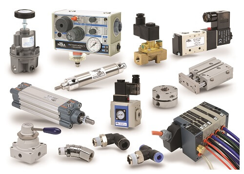
There are many components connected to create a complete pneumatic system. Nearly all pneumatics systems consist of these items:
- A method of generating compressed air to power the system. This is usually a plant air compressor and often includes pressure tanks, for reserve air, and distribution piping to machines and equipment.
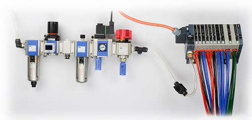
- A method of conditioning the compressed air, both at the compressor and locally, at the machine. All pneumatic motion requires clean and dry air with enough flow and pressure to perform the work. The process of filtering, regulating and lubricating compressed air is known as air preparation, or air prep. Manufacturing plants include air prep at centralized compressors, and additional air prep is beneficial at each machine’s point- of-use. This includes a manual shutoff, a filter to remove dirt, oil and water as needed, a regulator to control the system pressure, and possibly a lubricator to lubricate the air when needed for air tools or similar. A “soft start / exhaust dump” valve is also often included for operator safety to shut off upstream pressure and quickly relieve motion causing downstream pressure (pneumatic energy) when de-energized during a safety event.
- A method of controlling the directional flow of air. These are typically one or more types of valves. A good choice in machine control would be a 5-way, 3-position, center-exhaust valve where the center off position dumps air from both sides of the cylinder when an emergency stop is pressed, and power is removed. This valve typically operates using two 24 VDC solenoids. Energizing individual solenoids extends or retracts its corresponding cylinder.
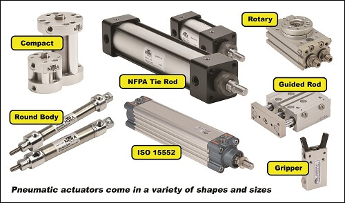
- One or more air-driven work devices. These can be linear or rotary actuators (cylinders), grippers, motors, air nozzles, etc.
- A collection or fittings and piping to connect all the components of a pneumatic system. These include rigid pipe and tubing or flexible tubing or hoses. Most cylinders include flow controls to both ports, to limit the cylinder speed by restricting air as it leaves the cylinder.
Pneumatic systems are common in industrial machine automation. Be sure to supply, prepare and distribute the air properly. When correctly selected, assembled and installed, pneumatic devices and actuators will have a long, efficient life with limited maintenance required.