Pneumatics are often the best fit for executing mechanical motion in a reliable, simple, and cost-effective manner.
Pat Phillips is the Product Manager for Fluid Power and Mechanical products at AutomationDirect, and he authored an article for the June 2019 issue of Tech Briefs titled Pneumatics for Mechanical Motion. Here’s a summary, click on the link above for the full text.
For equipment and machinery, fluid power is a term describing how mechanical motion can be achieved via hydraulics using incompressible liquids, or pneumatics using compressible gases like air or nitrogen. Pneumatics provides several advantages over hydraulics in many applications and has been a popular choice for industrial applications for over 100 years. Many consider compressed air a fourth utility after electricity, natural gas and water.
Typical Applications
Automated equipment commonly requires two-position and multi-position motions like clamping, gripping, positioning, lifting, pressing, shifting, sorting and stacking. For instance, a pick-and-place machine could use pneumatics to move a gripper through vertical and horizontal motions. Variable force control for applications such as tensioning and embossing is also possible.
Power Transmission Options
Pneumatic and hydraulic systems easily create linear motion using cylinders, whereas electrically driven systems would usually require other mechanisms to translate rotational into linear motion. Here is a table comparing linear motion with pneumatic, hydraulic and electric methods.
| Characteristic | Pneumatic | Hydraulic | Electric |
| Complexity Medium/High | Simple | Medium | Medium/High |
| Peak Power | High | Very High | High |
| Size | Low size/force | Very Low size/force | Medium size/force |
| Control | Simple Valves | Simple Valves | Electronic Controller |
| Position Accuracy | Good | Good | Better |
| Speed | Fast | Slow | Fast |
| Purchase Cost | Low | High | High |
| Operating Cost | Medium | High | Low |
| Maintenance Cost | Low | High | Low |
| Utilities | Compressor/power/pipes | Pump/power/pipes | Power Only |
| Efficiency High | Low | Low | High |
| Reliability | Excellent | Good | Good |
| Maintenance | Low | Medium | Medium |
Some machines may operate using pneumatics entirely, but it is also common for larger machines to use two or three of these power transmission methods.
Function, Simplicity And Economy
Fluid power systems typically produce more power in a smaller footprint than electric systems, with less complex automation integration. Hydraulic systems can be the most expensive method and are best used where the high peak power output is required. Pat describes other pneumatic advantages:
Pneumatic equipment generally has lower up-front design requirements than other options and is overall the least expensive. Not only are the installation materials and components relatively economical, but once a pneumatic system is in operation, the maintenance such as replacing seals or even a whole cylinder is often much cheaper than servicing, let alone replacing, an electric actuator. Troubleshooting can also be easier for pneumatic systems compared to electric.
There are some pneumatics downsides. Older systems have been regarded as noisy, but this has been largely remedied by modern components. Electrically-driven compressors are required to provide a source of pressurized air, adding energy conversion costs.
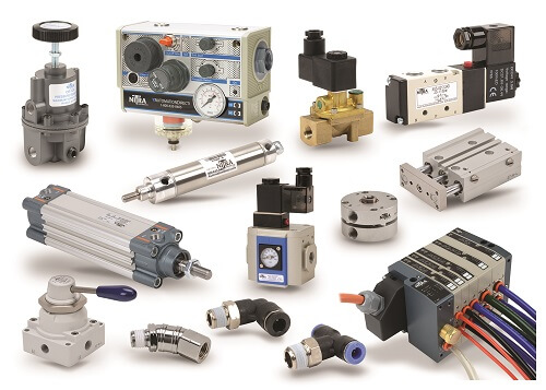
Pneumatic Hardware Basics
Most industrial facilities already have compressed air systems in place, and once it is delivered to a machine it is handled by these common pneumatic components:
- Air preparation system (shutoff/lock-out, combination filter/regulator, soft start valve)
- Tubing, hoses, and distribution manifolds
- Push-to-connect fittings
- Control valves and manifolds (manual, air pilot, solenoid-operated)
- Air cylinders and actuators
- Cylinder position sensors
- Discrete pressure switches
- Specialty components and accessories
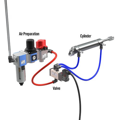
A basic pneumatic system would include air preparation, tubing, a control valve and a cylinder.
In the article, Pat details the functionality of each component, and also points out some good design practices.
An electrically operated soft-start valve serves two purposes. The first is to slowly pressurize the downstream system when energized so devices don’t slam into position. The second is to quickly dump air pressure downstream during an emergency stop, guard open, or similar safety event so actuated equipment stops as quickly as possible.
There are many options when designing pneumatic systems. Users can get quite elaborate, but the basics are quite straightforward.
Pneumatic Design Basics
Pat says designers should consider the mechanics first, and the automation features like control valves and position switches second.
The best design practice is to start at the actuators and mechanically determine the required force, stroke length, and speed. This will drive the compressed air requirements, from which the designer can work backwards to size the upstream supply elements.
Electric motion systems can offer highly accurate and programmable motion, and hydraulic systems are sometimes needed to achieve very high levels of force. But for many industrial equipment applications, the scales are tipped in favor of pneumatic systems for achieving mechanical motion because they offer the best combination of functionality, simplicity and economy.
Read more articles about pneumatics here.