When choosing the type of input or output module for your PLC system, it is very important to have a solid understanding of sinking and sourcing concepts. Use of these terms occurs frequently in discussion of input or output circuits. It is the goal of this post to make these concepts easy to understand, so you can make the right choice the first time when selecting the type of I/O points for your application. This post provides short definitions, followed by general example circuits.

First you will notice that the diagrams on this page are associated with only DC circuits and not AC, because of the reference to (+) and (-) polarities. Therefore, sinking and sourcing terminology applies only to DC input and output circuits. Input and output points that are sinking or sourcing can conduct current in one direction only. This means it is possible to connect the external supply and field device to the I/O point, with current trying to flow in the wrong direction, and the circuit will not operate. However, the supply and field device can be connected correctly every time based on an understanding of sourcing and sinking.
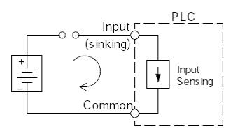
The figure below depicts a sinking input. To properly connect the external supply, it must be connected so the input provides a path to supply common(-). So, start at the PLC input terminal, follow through the input sensing circuit, exit at the common terminal, and connect the supply (-) to the common terminal. By adding the switch between the supply (+) and the input, the circuit is completed. Current flows in the direction of the arrow when the switch is closed.
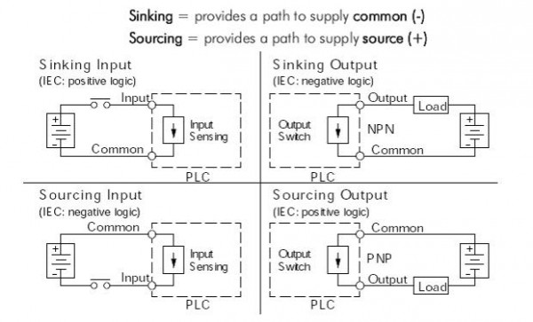
The four possible combinations of input/output sinking/sourcing circuits are shown below. The common terminal is the terminal that serves as the common return path for all I/O points in the bank.
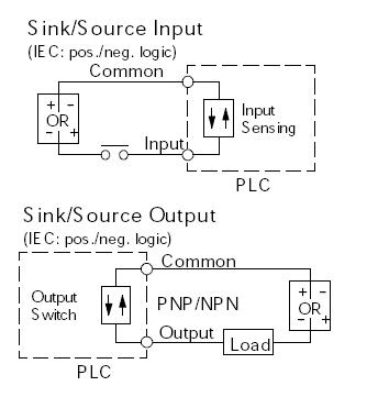
Sink/source I/O circuits combine sinking and sourcing capabilities. This means that the I/O circuitry in the PLC will allow current to flow in either direction, as shown below. The common terminal connects to one polarity, and the I/O point connects to the other polarity (through the field device). This provides flexibility in making connections to your field power supply.
Please Note:
- Wire all I/O points with a shared common as either sinking or sourcing.
- Do not use an AC power supply on a DC sink/source I/O point.
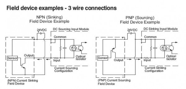
Below are detailed electrical diagrams for sinking and sourcing configurations, showing typical PLC input module and field device circuitry.
Common Terminals and How to Use Them
In order for a PLC I/O circuit to operate, current must enter at one terminal and exit at another. This means at least two terminals are associated with every I/O point. In the figure below, the input or output terminal is the main path for the current. One additional terminal must provide the return path to the power supply. Together, the main path and the return path create a loop, or a complete circuit for current to flow.
If there was unlimited space and budget for I/O terminals, then every I/O point could have two dedicated terminals. However, providing this level of flexibility is not practical or even necessary for most applications. So, most input or output points on PLCs are in groups that share the return path (called commons). The figure below shows a group (or bank) of four input points that share a common return path. In this way, the four inputs require only five terminals instead of eight.
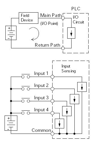
NOTE: Assuming all input circuits have a similar resistance, the current at the common terminal is four times greater than the current at any one of the inputs. This effect is especially important to note for output circuits, where the current through a common terminal can reach several amperes. You will need to decide whether to fuse each output point individually, or to put a fuse in the common terminal path.
Click here to read more articles about Programmable Controllers.