Part presence sensing is a critical part of automation. A controller must often sense a part is present in a fixture, or sense the part position on a conveyor, to make logic decisions such as run, stop, etc.
Presence sensor types include photoelectric, inductive, capacitive and others—and this abundance of choices can complicate specifying the sensor as each type has its strengths and weaknesses. It can be argued that the photoelectric sensor fits the widest range of applications due to its capabilities and varied types, technologies and configurations, including:
Common photoelectric sensor light emission types:
- Infrared
- Visible red
- Laser Class 1 and 2
Common photoelectric sensing technologies:
- Diffuse – it bounces light off the part, using the part as the reflector
- Reflective – it bounces light off a reflector, which is often polarized
- Through-beam – it has two separate sensor heads, a light emitter and a light receiver
- Background suppression – Similar to diffuse but typically a more focused light, and possibly triangulated
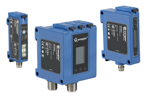
Photoelectric housing configurations:
- Photo eye – electronics and optical sensor head both in one unit
- Fiber optic – separate amplifier connected via a fiber optic cable to an optical sensor head
Lighting Up an Amp
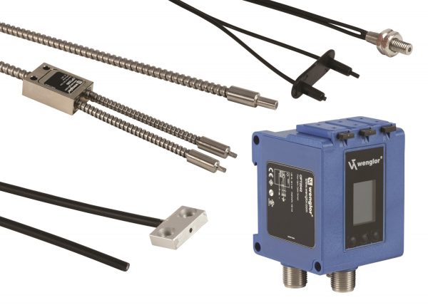
Fiber optic sensors typically include two devices that must be specified, the amplifier and the fiber optic cable. The amplifier is sometimes referred to as the electronics or photoelectric amplifier. The fiber optic cable is actually two devices specified as a single device. It includes the optic sensor head and the fiber cable that transmits light to and from the amplifier.
The fiber optic cable can include the emitter and receiver in one optical sensor head, a configuration often used with diffuse and reflective devices. Alternately, there can be two separate cables, each with an optical sensor head, as used in through-beam devices. This is similar to how standard photo eyes are configured, but with the addition of fiber cable to transmit and focus the light.
Amplifying Light for Input
Fiber optic amplifiers are available in many styles ranging from basic plug-and-play to highly configurable. To handle large installations, some fiber optic amplifiers can be part of a rack or manifold-like configuration with the ability to accept up to 15 sensor inputs.
There are many specifications to consider when ordering fiber optic sensors including:
- Output contact configuration – normally open (NO) or normally closed (NC)
- Output type – PNP (sourcing, U.S. standard) and NPN (sinking)
- Wiring – cable or quick disconnect with standard M8 or M12 connections
- Signal strength indicator or OLED display – adds local indication
- Filtering, pulse output, on/off delay – modulates the sensor output
- Sensitivity adjustment – digitally programmable or manual potentiometer
- Teach function – automatic level setting procedure
Transmitting Light with Fiber Optics
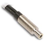
Fiber optic cables transfer diffuse, reflected light or through-beam light from the integral optical sensor head to the amplifier. A wide variety of fiber optic cables are available with different fiber types and optical head designs. To help narrow down the choices, the selection process starts at the part being sensed with the following considerations:
- Optic cable selection – diffused (singe fiber cable) or through-beam (two fiber cables)
- Fiber type – plastic (thinner, low cost and flexible) or glass fiber (rugged and suitable for high temperature installations)
- Optical sensor head – careful selection is required due to multiple options including physical dimensions, mounting, light beam diameter and sensing range
- Sensing range – depends on amp, fiber cable length and optical sensor head
- Fiber environmental ratings – some cables can be fragile.
Applying Fiber Optics
Fiber optic sensors are touted for their immunity to electrical noise, such as the electrical magnetic interference (EMI) common in welding applications. The fiber optic cable, which is immune to electrical noise, allows the amplifier to be mounted away from the EMI. However, that’s not their main application.
The fiber optic sensor’s light shines brightest in part sensing applications on automated machines. Error proofing and confirmation of part placement plays a big part in automated assembly applications. The controller needs to know the part is present and fully seated in position, and fiber optics provide precise position sensing of the parts, sensing even small movements. This is possible through proper selection of the optic sensor head, and focusing of the light if necessary, to catch the edge of a part.
In any fiber optic installation, always be sure to eliminate excessive flexing or too tight of a bend radius. Refer to the specifications when in doubt. Too much flexing will break the fiber cable just as it would a wire. Also, too tight of a bend radius can deform the fiber and reduce or stop light transmission. A crushed fiber optic cable displays the same issue, so buy an armored fiber cable or install the cable in a small tube, such as used in pneumatic circuits, to protect it from damage.
Whatever the sensing application, the designer must define the requirements and carefully select the sensor technology. With fiber optic sensor, once the amplifier is selected, select both the fiber cable and integrated optical sensor head carefully or your machine may not see the light.
For more information, please see the How to Specify Fiber Optic Sensors article in the October 2016 issue of Machine Design, authored by Andrew Waugh, Sensor and Safety Components Product Manager at AutomationDirect.