When relays and timer circuits get old, they cause problems. Replacing them with PLCs keeps pumps running smoothly.
One of the most important jobs of a water distribution system is to reliably deliver water to its customers. At our water district in California, we had pumping stations (Figure 1) with relay-based controls that were more than 30 years old, and the vintage of the controls caused a definite reliability issue.
 A typical pump station has three or four pumps, each powered by 100 or 125 horsepower motors. Because of the relatively large motor size, a part winding motor starting system is used with two motor starters. When the pump is turned on, the first motor starter is energized. Then, after a time delay, the second starter is energized. Two types of timers were used in the control logic, pneumatic and electronic. As the pneumatic timers aged, they lost their timing repeatability. It was common to hear the motor strain while waiting for the second starter to pull in.
Electronic timers were sometimes even worse as their electrolytic capacitors failed over time. When the timers failed it was hard on the motor because it was running on only one starter until the overload tripped.
Personally, I’ve had to replace more of the electronic timing relays than any other device in the control circuit. I thought it was time to upgrade the pump controls and my company agreed, so we decided to investigate alternatives.
Taking a Test Drive
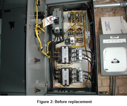
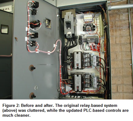
We decided to do a pilot test on two stations over a one-year period. We replaced all the pneumatic and electrical relays with DL05 PLCs from AutomationDirect (Figure 2). The PLCs were installed inside the motor control center (MCC) buckets by our in-house district electricians.
When the first pilot pump control circuit was changed over to PLC control, I set the delay time between the activation of the two motor starters to 0.5 seconds. Our control electrician didn’t like the way the motor sounded, so with one quick edit I set the timer to 0.4 seconds. We’ve never had to readjust them since, and there’s no longer any drift in the timing because the PLC is a digital device.
We were concerned about how well a PLC would hold up in the hot and electrically noisy environment of an MCC without cooling or a UPS, but they have proven to be very robust. The only failure we had was when a pump control valve’s solenoid shorted out and pulled an excessive amount of current. Installing a fuse on the output solved the problem. It should be noted that this failure was our fault as we should have installed an output fuse in the first place.
We’ve since installed about 55 DL05 PLCs in our pumping stations, one on each motor, with no reliability issues in more than a decade of service.
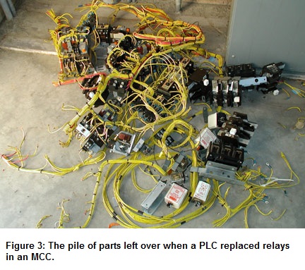
Another advantage is the PLC simplifies and enhances pump operation. A typical MCC had hundreds of wires and dozens of relays (Figure 3) in multiple buckets. In some cases the wire numbers had fallen off over time, which made troubleshooting very difficult. In addition, the control logic only provided one alarm pump timeout. When a pump failed to start properly, we were never sure why it had failed.

The specific problem was that when a pump failed to operate properly, it would time out and couldn’t be restarted until manually reset by an operator. This reset cleared the timeout relay logic, making it hard for the technician to troubleshoot the problem.
Now, the PLC is programmed so the alarm can be reset by the operator; this allows the pump to run, while maintaining failure information in the ladder logic until the relevant area of the PLC program is reset by the technician. This gave us better flexibility in that a failed pump can be returned to service without losing information vital to the troubleshooting process.
Another enhancement was to expand the type of alarms sent back to the central SCADA system. Now, the alarm is defined three different ways: pump fail, MCC fail, or pump control valve fail. Before the upgrade, it was common to have a few pumps fail to start every week, but that’s no longer the case.
Dealing with Water Hammer
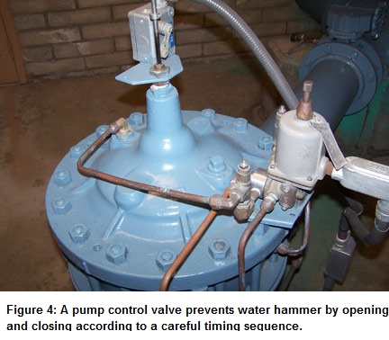
In a water distribution system, another area of concern is always water hammer. Water hammer occurs when water flow is halted abruptly, causing a shock wave to travel through the line. The force of the shock wave can cause severe damage to critical control parts. When a large pump is started in our water pumping application, a pump control valve is used on the output of the pump to stop the possibility of a water hammer (Figure 4).
The motor is started into a closed pump control valve, and the valve is allowed to open slowly. On shutdown, the valve is closed slowly and a micro-switch notifies the controller to turn off the motor. Here’s the sequence of events that occur when a large pump is started:
1. The first motor starter pulls in
2. The second motor starter pulls in
3. The pump control valve is commanded to open
4. The pump control valve is monitored to ensure it fully opens
Every step is timed, and if there’s any failure of the proper sequence the motor is automatically turned off. The pump is then held out of service until an operator investigates the problem and pushes a reset button.
The old system was a nightmare to troubleshoot with its pneumatic and electrical relays. Now, with the PLC, finding the source of the problem is much easier. The PLCs have allowed us to solve our control issues at a low cost with high reliability. We still use the brick style DirectLOGIC DL05 PLC in existing MCCs, but in our new MCCs we’ve upgraded to the DL06 PLC, which has more expandability and a local LCD display option. We expect similar reliability from the DL06 PLCs, along with continued ease of use and superior vendor support.
By Henry Palechek
Process Control Supervisor
About the Author
Henry Palechek is the information systems and process control supervisor at a water utility in California. He’s been with the utility for over 16 years. He holds a Bachelor of Science in Information Systems, and has been teaching water technology courses at the local community college since the mid 90s. He also holds a California T3 Operator license.
Originally Posted: June 1, 2011


