Why Calibrate?
Many applications call for a means to take accurate analog measurements. Force, pressure, electrical current, lengths, positions and other analog values that are measured must be done so with a degree of accuracy. Factory and lab personnel use calibration procedures to ensure that equipment is reading accurately. If the readings are not as accurate as required, a calibration procedure should allow for the implementation of a correction factor. Personnel operating the equipment can perform their jobs more readily if the measurement system can easily be checked for accuracy and calibrated. Ideally, the process would be transparent to operators who do not need to understand the details of the operating system and only need to see and understand the measurement results reported by the equipment.
An engineer designing a measurement system will generally examine the voltage or current to be provided by the measuring transducer and the “counts” that should result after the analog input card converts the electrical signal to a number. The conversion factors can be set up to convert counts to real world units such as pressure or force. These theoretical or ideal factory published numbers are suitable for specifying equipment, but when the system is set up and running, the actual readings and numbers will differ from the theoretical. Wires will add resistances that cannot be calculated in advance and temperature changes will cause variations that must be accounted for. No analog system will run exactly per “book values” and thus a calibration routine must correct for the differences.
Calibration Method
The calibration method described here can be applied to any analog measurement such as pressure, amperage, weight, length or force. Let’s consider an example where the length of an object is being measured. We will assume that a device has been built that converts the length of the object to numerical readings via the analog input. The type of instrumentation used may be a laser measuring device, an LVDT, or any device that provides an analog signal that will vary with the length of the object being measured. We will assume the following:
1. The object being measured ranges from 2 to 9 inches in length and the analog device is capable of measuring over this range.
2. The analog device provides a voltage signal to the analog input card. The voltage is converted to a number or “counts” by the analog card. The “count” resides in real time in a register in the PLC and the ladder logic can perform math functions using this number. For example, let’s assume that an object is being measured 2 inches in length and the count is 100, and when an object 9 inches in length is measured the count is 3900.
The nice thing about the method described here is there is no need to be concerned with the amount of voltage provided by the transducer or received by the analog input card. By utilizing the counts and then converting the counts directly to length, the voltage becomes irrelevant as long as any change in counts is linear with any corresponding change in length. This provides the advantage of not needing to be concerned with calibration or setup of the transducer and its amplifier. Too often, time is spent setting the “zero” and “span” of amplifiers and signal conditioners where a person might determine: “This object measures 2.3 inches, therefore my voltage should be 1.2 volts”. Then they proceed to set the zero and span to achieve an exact voltage for the corresponding length. By using the calibration method described here, this process is no longer necessary and the exact voltage at any given length is of no concern. Time is saved because the calibration of the amplifier’s voltage is now rolled into the software calibration of the entire system. Additionally, if someone comes along later and adjusts the zero or span, the calibration procedure described below can be run and the PLC program will compensate for the changes.
Calibration Procedure
Calibration routines are often set up to simply add in a correction factor; but this “one point” method leaves room for error over a range of readings. A car speedometer that is permanently stuck at 60 mph will appear accurate if checked when the vehicle is moving at 60 mph. A better calibration method uses two points; a “low point” and a “high point” and then calculates a line that goes through both points. We will use a 2-point calibration, which requires two calibration units of specific lengths. We will call these units “calibration masters”. In our example, they can be any length within the readable linear range. Let’s assume that one is 4.2 inches long and the other is 6.8 inches long.
Four values will be captured during the calibration procedure:
a. The actual length of the “low” calibration master (4.2 inches)
b. The analog reading (counts) when the low master is
measured
c. The length of the “high” cali- bration master (6.8 inches)
d. The analog reading (counts) when the high master is
measured
From this point forward the four values, a through d, will be used to set up the math required to covert counts to inches. We will call the resulting value “e”.
The change in length for any corresponding change in counts is calculated as follows:
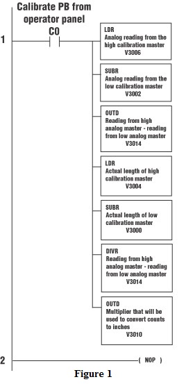
(c-a)/(d-b) = e
The person performing the calibration enters the lengths of the high and low calibration masters (values a and c) via the operator interface and these values are stored in PLC registers. The corresponding analog counts for the high and low calibration masters (values b and d) are captured during the calibration routine and are also stored in PLC registers.
We will use the following data registers:
a = “low” calibration master = Register V3000 / V3001
b = low master analog reading = Register V3002 / V3003
c = “high” calibration master = Register V3004 / V3005
d = high master analog reading = Register V3006 / V3007
The following ladder logic will calculate “e” and store this value in V3010/V3011. Data register V3014 is used to store temporary math results while the accumulator is in use performing other math. See Figure 1
Length Conversion
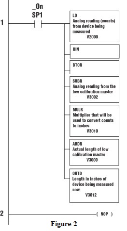
After the calibration routine has been run and the values a through e are stored in the PLC, the formula for converting counts to length is:
((counts – b) x e) + a
The following ladder logic will calculate the length from the counts and store the resulting length in V3012/V3013. The analog reading from the device being measured is stored in register V2000. See Figure 2
Some of the advantages of this calibration procedure are:
Because the user chooses the calibration points, calibration masters can be at any length. Calibration masters no longer need to be made to a specified predetermined length.
If a specific range is the most critical, the calibration can be done at that specific range. In the example above, if the most critical readings are between 3.5 and 4.2 inches of length, the calibration masters can be approximately 3.5 and 4.2 inches. In this way, calculating the straight line over the critical range minimizes any non-linearity in the system and provides the most accurate readings in the critical range.
By displaying the actual calculated length and the analog counts on the operator interface, anyone who desires can follow along with the PLC and observe the math in action. This makes the system’s internal workings clear to anyone using the equipment.
By Gary Multer,
MulteX Automation
Originally Published: Sept. 1, 2004


