Upgraded alarm and monitoring systems keep fish and Alaska’s economy alive.
Alaska leads U.S. states in the value of its commercial fishing catch. The Alaska salmon industry represents the world’s only sustainable salmon fishery. And with seafood being Alaska’s largest export, excluding oil and gas, the Alaska hatchery system plays a vital role in the state’s economy. Salmon hatcheries in Alaska are directly funded by, and directly support, the fishing fleets and fishing industry.
Our facility, Hidden Falls Hatchery, is operated by the Northern Southeast Regional Aquaculture Association. It’s located on Baranof Island at Kasnyku Bay on Chatham Strait and is accessible only by boat or float plane (Figure 1). Hidden Falls is one of the largest fishery enhancement programs in Southeast Alaska.
 Some attempts were made in the past to automatically monitor the facility. A PLC installation was started in 1991 to monitor the vacuum system, but it was never completed. The PLC had a CPU fault, so the project was scrapped. The hatchery site was, in essence, unmonitored—and the value of monitoring critical systems at hatchery sites can’t be overemphasized.
We needed a fully functional automation and alarm system to monitor the processes vital to keeping the fish alive and healthy. The goal was to have a fully integrated alarm and monitoring system covering all aspects of the site, especially the aquaculture fish cultivation systems.
We researched our options and designed a system to monitor the site. We chose DirectLOGIC DL06 PLCs, C-more 15- and 6-inch touch screen HMIs, and a Stride unmanaged Ethernet switch, all from AutomationDirect. We also selected a NetGear managed switch, Ubiquiti Networks PicoStation access points, as well as AutomationDirect ProSense temperature and pressure transmitters.
Hidden Falls Hatchery Facility

Because of its remote location, Hidden Falls Hatchery must operate sustainably to support the site’s aquaculture, mechanical systems, and residences. The hatchery’s aquaculture includes the main incubation building, a secondary incubation building, and two fields of circular rearing containers (Figure 2). See the sidebar “Salmon Life Cycle and the Hatchery Process” for further hatchery operation details.
The mechanical systems include the vacuum building, the hydroelectric building, and the maintenance shop. The site also supports six housing units and a bunkhouse used for temporary and seasonal employees.
The new alarm and monitoring system alerts the small onsite staff immediately if a problem is detected. This allows our staff to monitor incubation and rearing container water levels and flows—and also track runtime on equipment, monitor trends and analyze abnormal conditions.

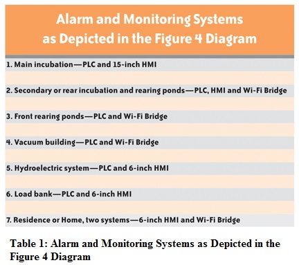
The main hatchery building houses the primary incubation PLC and 15-inch HMI (Figure 3), which also serves as the main alarm panel for the hatchery. This PLC/HMI system connects to the hatchery’s Ethernet LAN through a NetGear managed switch. The hydroelectric and load-bank PLC/HMI systems as well as a Wi-Fi Bridge connect to the LAN through the Stride unmanaged switch (Table 1 and Figure 4).
In addition, two residence-mounted 6-inch touchscreen HMIs connect to the LAN via Ethernet. In cases where the PLC is in close proximity to the HMI, communication is handled using AutomationDirect’s DirectNet Link. Where the PLC is at some distance from an HMI—as with the vacuum building and front round pond PLC—the network connection is made with an ECOM100 Ethernet module and Wi-Fi bridge.
The HMIs are essentially the only direct means for user input. Each alarm can be acknowledged or disabled from its associated HMI. We can change setpoints from the HMI as well. With this system, any HMI can see everything that’s happening on the hatchery site. This visibility is very important to our small staff.
We divided the monitoring and alarm duties according to the type of process to be protected: aquaculture or mechanical systems. Due to the distances between parts of these systems, we further divided the system by using multiple PLCs placed in close proximity to the systems they monitor or control. Alarms for each system are interpreted by that system’s PLCs.

Monitoring Hatchery Aquaculture
Survival of the fish depends on the reliability of the alarm system monitoring the hatchery’s critical processes. Every part of the hatchery’s water flow from the supply lake on down to the sea can impact the water flowing to the fish. The earlier we can detect a problem upstream, the more likely we’re able to head off situations that could affect the salmon fry.
 Incubation is the heart of any hatchery operation. Water for the incubators passes through six head boxes: four in the main incubation area and two in the rear incubator area. Head boxes are open-air troughs that supply low-pressure water to the incubators (Figure 5). They’re positioned several feet above the incubators and use gravity flow to supply the water.
The head box alarm system monitors the incubators. Low or high head box levels can result in loss of water to salmon fry. Loss of a single incubation row could result in losing millions of fish, which could have an enormous economic impact on the Southeast Alaska fisheries.
Head boxes are monitored continuously using 0-100-inch water column pressure sensors, which allow us to measure levels to the nearest 0.1 inch. These pressure sensors connect to the analog inputs of their respective PLCs for the main and rear incubation areas. The continuous readouts on the HMIs provide visual evidence that the pressure sensors are working.
Three PLCs monitor critical aquaculture parameters by receiving sensor information via their DC inputs:
1. Main incubation alarm system consisting of a PLC and a 15- inch HMI
2. Rear incubation and rearing pond alarm system consisting of a PLC, 6-inch HMI, and a Wi-Fi node
3. Front rearing pond alarm system consisting of a PLC and a Wi-Fi node.
These PLCs monitor water levels and flows on all of the incubation and rearing containers. Float switches connected to the discrete inputs of the appropriate PLCs monitor rearing container water flow.
Monitoring the Hatchery’s Mechanical Systems
Two other PLCs monitor the hatchery’s mechanical systems, namely the vacuum building and the hydroelectric building. The hydroelectric building contains the automated load-bank control system. These PLCs and their associated HMIs allow us to track equipment runtime, monitor trends, and analyze causes of abnormal conditions.
The vacuum building is located near Hidden Falls Lake, which is a 15-minute hike up the hill. The vacuum building alarm system consists of a PLC and Wi-Fi node at the vacuum building. The vacuum system alarms are transmitted wirelessly, and displayed and acknowledged at the incubation HMI in the main hatchery building. Personnel can meet there to discuss alarm conditions before climbing up the hill, which can be quite an adventure in winter.
The vacuum building houses a pair of duplex 2.6-hp liquid-ring vacuum pump systems that maintain vacuum on their respective pipelines. Vacuum system parameters are monitored by the PLC, and are relayed to our main incubation alarm system over Wi-Fi. The PLC monitors and alternates runtime equally for each vacuum pump.
We’re off the grid, so we get our power from our 250 kW hydroelectric turbine/generator. Water for the turbine/generator is fed from the lake through two large pipelines. We also have a standby generator and a load bank. The hydroelectric and standby generators are tied to the load bank, which dynamically adjusts system load to maintain desired water flow. The load bank is controlled and monitored by a PLC and a 6-inch HMI, connected to the Ethernet LAN.
The hydroelectric turbine/ generator’s monitoring and alarm system consists of a PLC and a 6-inch HMI. An illuminated annunciator board displays turbine/generator, backup generator, diverter, and load-bank related alarms.
The hydroelectric PLC monitors water temperature and pressure; oil temperature, pressure, and level; and transfer switch position. This PLC also monitors the automatic diverter system, which provides water for the hatchery if the turbine/generator trips.
Alarming Success
Since the hatchery’s integrated monitoring and alarm system was installed, it has alerted us to several major situations that would otherwise have gone undetected, each of which would have been emergencies.
On several occasions, clogged intake screens on the head box water supply resulted in low head box water levels. The alarm system alerted the staff before any loss of water to the fish actually occurred.
The HMI tells the staff exactly what causes an alarm condition. If high or low head box alarms occur, the HMI identifies the specific head box. In addition, the water levels are continuously charted and recorded, allowing staff to determine exactly when and how the alarming condition occurred. Each HMI accommodates a USB thumb drive where we log files of every alarm and charts for virtually every parameter we monitor.
On another occasion, a condition at the hydroelectric plant turned into a loss-of-power emergency. Water pressure dropped too low to meet turbine/generator water demand, which also affected water flow to the head boxes, and the head box water level dropped below the alarm setpoint. The resulting head box low water alarm preceded the loss of power alarm by about 1 minute, allowing us to take corrective action.
The equipment from AutomationDirect allows us to continuously monitor the water supply and mechanical systems as a whole. The new alarm system allows us to spot previously undetected issues before they cause more trouble.
The determining factor for choosing solutions from AutomationDirect was pricing. However, we’ve since realized additional benefits from the variety of available add-on PLC modules, the user-friendly software, and the extensive technical documentation available on: www.automationdirect.com.
AutomationDirect service has also been first-rate, and the technical support and the technical forums have been extremely valuable. We sometimes feel quite alone in our isolated location, so it’s good to have a partner that we know will be there to answer our questions.
Salmon Life Cycle and the Hatchery Process
Hidden Falls Hatchery rears more than 100 million chum salmon, and several million Chinook and Coho salmon, all of which are released each year as smolts. Smolts are young salmon that leave fresh water to go to the sea. In three or four years, the salmon return to fresh water to spawn. Because of their homing instinct, the fish seek the fresh water from their childhood.
From the ocean, the returning fish come into Kasnyku Bay. We carefully segregate a portion of the returning fish into a small portion of the bay enclosed by a barrier net. These fish are then referred to as brood stock. The brood stock are admitted into a fresh water lagoon in controlled numbers using a weir.
When they are ready, we start water flow to a fish ladder that leads to several raceways. Fish in the raceways are then spawned by a crew of about six people. The eggs and sperm are extracted and combined. The fertilized eggs are then placed into incubators.
Water from Hidden Falls Lake operates the turbine/generator at the hydro-electric building. The discharge water feeds the low-pressure hatchery water supply, which in turn feeds the incubators and rearing containers. Any failure or mistake at this point could kill millions of fry, or young fish. This is true until the fish are introduced to their saltwater rearing pens or directly released to the sea.
After an incubation period of several months, the fry are introduced into saltwater rearing containers. Maintaining water flow to these containers is vital. If the water flow is stopped or significantly altered, the oxygen in the water is quickly used up, resulting in mortality of the fish.
By Benjamin Smith
Maintenance Supervisor,
Hidden Falls Hatchery, Sitka, Alaska
Disclaimer: AutomationDirect does not guarantee the products described in this article are suitable for your particular application, nor do we assume any responsibility for your product/system design, installation, or operation.
Originally Posted: March 1, 2012