There are thousands of industrial applications that require a linear motion during their operation sequence. One of the simplest and most cost effective ways to accomplish this is with a pneumatic actuator. Pneumatic actuators are also very clean operating because the operating fluid is a gas, which prevents leakage from dripping and contaminating the surroundings.
This section will discuss the basic construction and function of a pneumatic actuator, the relationship with a fluid power system and the selection guidelines for pneumatic actuators or air cylinders.
Basic Styles – Pneumatic Actuators
Pneumatic actuators convert compressed air into rotary or linear motion. There are many styles of pneumatic actuators: diaphragm cylinders, rodless cylinders, telescoping cylinders and through-rod cylinders.
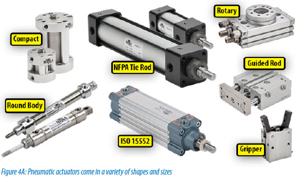
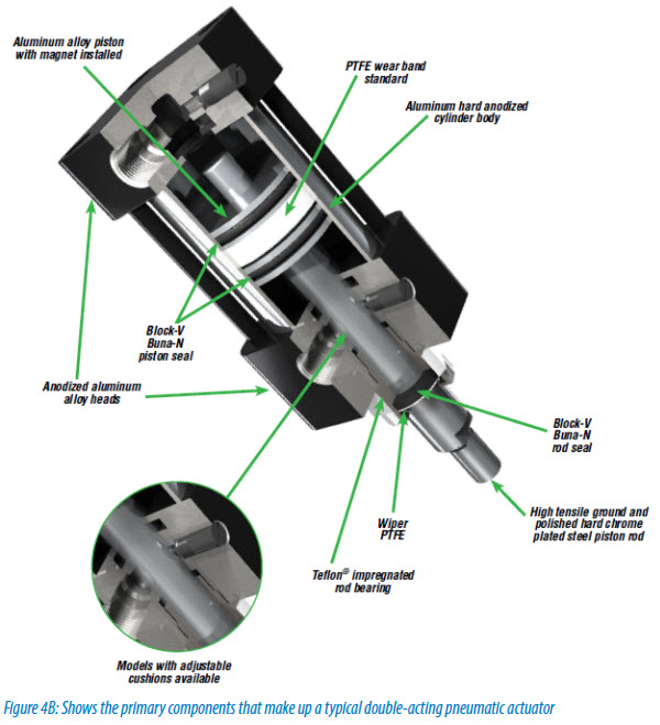
The most popular style of pneumatic actuator consists of a piston and rod moving inside a closed cylinder. Even so, there is a large variety of construction techniques and materials to fit a wide range of applications and user preferences. Body materials can be aluminum, steel, stainless steel and even certain polymers. Construction can be either non-repairable or repairable. This actuator style can be sub-divided into two types based on the operating principle: single acting and double acting.
Single-acting cylinders have a single port to allow compressed air to enter the cylinder to move the piston to the desired position. They use an internal spring or sometimes simply gravity to return the piston to the “home” position when the air pressure is removed. Single-acting cylinders are a good choice when work is done only in one direction such as lifting an object or pressing an object into another object.
Double-acting cylinders have a port at each end and move the piston forward and back by alternating the port that receives the high pressure air. This uses about twice as much energy as a single-acting cylinder, but is necessary when a load must be moved in both directions such as opening and closing a gate.
In a typical application, the actuator body is connected to a support frame and the end of the rod is connected to a machine element that is to be moved. A control valve is used to direct compressed air into the extend port while opening the retract port to atmosphere. The difference in pressure on the two sides of the piston results in a force equal to the pressure differential multiplied by the area of the piston. If the load connected to the rod is less than the resultant force, the piston and rod will extend and move the machine element. Changing the valve to direct compressed air to the retract port while opening the extend port to atmosphere will cause the cylinder assembly to retract back to the “home” position.
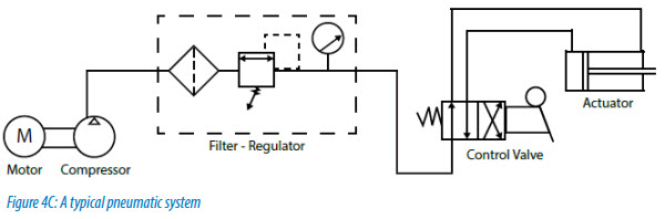
Pneumatic actuators are at the working end of a fluid power system. Upstream of these units, which produce the visible work of moving a load, there are compressors, filters, pressure regulators, lubricators, control valves and flow controls. Connecting all of these together is a network of piping or tubing (either rigid or flexible) and fittings.
Pressure and flow requirements of the actuators in a system must be taken into account when selecting these upstream system components to ensure the desired performance. Undersized upstream components can cause a pneumatic actuator to perform poorly or even make it unable to move its load at all.
Force
The above Figure shows a basic system to power and control a pneumatic actuator. When selecting an actuator it is important to properly match the cylinder to the job.
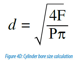
A typical pneumatic system configuration is shown in Figure 4C. The theoretical force available in the actuator is the piston area multiplied by the supplied air pressure. Spring force must be subtracted from this value for single-acting cylinders. The actual force of the actuator will be 3-20 percent less due to pressure losses in the system. A good rule to use when sizing an actuator is to select an actuator that has about 25% more force available than needed for the job, and the following formula can help with determining size requirements. Take a look at our Interactive Cylinder Bore Calculator here.
Speed
When the cylinder force (F) is known, the bore diameter(d) can be found by the above formula. F is the force required (lbs) and P is the supply pressure (psi). Stroke length is determined by the required travel of the machine element driven by the actuator. The speed at which the cylinder can move a load is directly related to the rate that the compressed air can flow through the pneumatic system to the piston to make it move.
This can often be a little tricky to calculate, since as the flow rate increases, system resistance (basically friction of the air moving through pipes and components) will increase in a non-linear fashion. The result is a larger pressure drop from the supply (air compressor) to the cylinder. When the pressure drop is so large that the available pressure at the cylinder cannot move the load, the cylinder will stall. When speed is critical to a machine operation, it may require testing two or three combinations of valves, tubing and cylinders to get the desired performance. Let’s look at a practical example of how you would figure out your requirements. See our “Rules of Thumb” for fast cylinder action along with our Interactive Theoretical Speed Table here.
 For example:
It is desired to move a 200lb load 12 inches at a rate of 20 cycles per minute. Using a 2” bore cylinder, about 64 psi is required to move the load.
Adding 25% gives an operating pressure of 80 psi. At the desired cycle rate and using 1/4” OD tubing (0.156” ID), pressure losses in the tubing are about 1.5 psi per foot.
It can be seen that the tubing run total (extend and retract lines) needs to be less than 10 feet or else the pressure losses due to friction will drop the available pressure at the cylinder below 64 psi and the cylinder will stall.
Once the cylinder stops moving however, the friction losses go away and the pressure builds back up to 80 psi. This situation results in a jerky motion of the cylinder as it moves the load.
Several factors could overcome this problem:
- System pressure can be increased to overcome friction losses
- Larger tubing can be used to reduce friction losses
- Different size cylinder could be tried that will reduce the flow
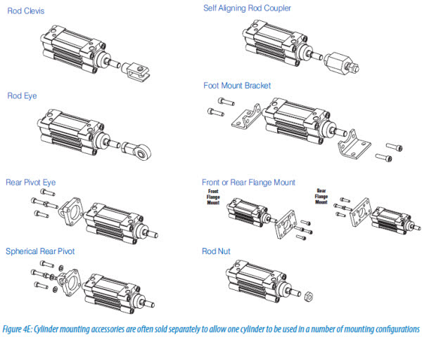
Mounting
The final bit of basic selection criteria is the cylinder mounting arrangement. There are many different configurations available from various manufacturers. The more common ones include rigid nose or tail mount, trunnion mount, rear pivot mount and foot mount. A study of the machine motion required usually will show which mounting configuration is the best choice.
Once the basic actuator size and configuration is known, other options such as end-of-stroke cushions, magnetic piston (for position detection switches) or special seals should be considered when making the final selection.
Cushions
Cushions do an excellent job of preventing a piston from banging into the end caps at the end of stroke. Flow control valves can prevent banging also, but at the expense of a slow travel speed. Cushions only slow the travel for about the last half inch of stroke. A cushion is very useful when the design requires a higher cycle rate or speed and also smooth starting and stopping.

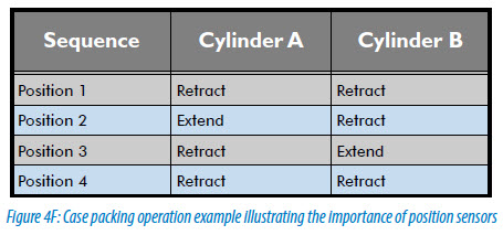
Magnetic Pistons
Magnetic pistons allow simple magnetic proximity sensors to be mounted on a cylinder which can allow a control system to get feedback on the position of a cylinder. Since most cylinders are either extended or retracted, two proximity switches can monitor the operation of a cylinder. This can be very beneficial for machines that require a sequence of operations. Due to the nature of compressed air systems , the exact speed of a cylinder may vary slightly due to a number of factors outside of the control of the machine’s control system such as supply pressure variations, moisture content in the air or ambient temperature. Therefore, a control sequence that begins Step 2 once Step 1 is confirmed complete and so on is a much more robust design.
Temperature Extremes
When it comes to sealing a pneumatic system, remember that environmental conditions such as temperature extremes or corrosive materials may require special seal materials such as Viton. Most manufacturers offer these special seals as an option.
Since pneumatic actuators are at the working end of a fluid power system, producing the visible work of moving a load, pressure and flow requirements of the actuators must also be taken into account when selecting upstream components. Undersized upstream components can cause a pneumatic actuator to perform poorly or even make it unable to move its load at all.