Pneumatic actuators are essential workhorses for implementing machine and equipment motion. Here are some pointers regarding different styles for control and monitoring.
Pat Phillips is the Product Manager for Fluid Power and Mechanical products at AutomationDirect, and he authored an article for the June 2019 issue of Fluid Power World titled Pneumatic Actuator Control Options. Here’s a summary, click on the link above for the full text.
Pneumatic actuators are a popular way to achieve motion for equipment and machinery because they are simple, cost-effective and durable. They are compact and powerful, and work well when the right configuration is selected. This article reviews some pneumatic actuator basics.
Pneumatic Actuator Basics
Pneumatic actuators convert the energy of compressed air into linear motion. Some basic styles are:
- NFPA tie-rod
- ISO 15552
- Round body
- Guided rod
- Compact
Here is how Pat describes the basic functionality of a pneumatic cylinder:
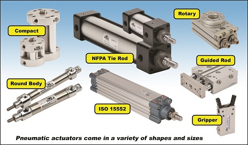
Air pressure supplied to or removed from the piston moves it and the associated rod. The shaft generates linear motion, and additional mechanisms may translate this motion into a rotary or gripping action. Pneumatic valves control the flow of compressed air supplied or discharged from one or both sides of a cylinder.
In addition to considering the geometry, mounting methods and sizing for the proper force, users need to plan for actuator control.
When to Enhance Control
Pneumatic actuator performance is impacted by air pressure, variable payloads and wear within the actuator or external mechanisms. When humans command actuators with manual controls, they can observe the action. However, automated systems need to use solenoids and sensors. According to Pat, many users choose to monitor all pneumatic actions for automated equipment.
Most cylinders operate to two positions, extended and retracted. By installing position switches for each case, the control system can be configured to alarm if a cylinder has not reached the commanded position when expected. It is also possible to add more switches to indicate when actuators reach midway positions.
Even more advanced automation is possible, such as monitoring the stroke time for a cylinder, and alarming when it takes too long or fails to move as commanded.
Choosing the Right Options
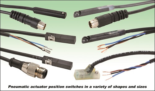
Position can be sensed on the actuator itself or on the driven equipment, depending on requirements. Installing sensors on-board the actuator is a proven method but will not identify an external failure in the driven equipment. Many actuators include T-slot, round or dovetail slots for convenient sensor mounting. Other sensors use mounting bands or adapter brackets.
Although older-style mechanical reed switches are still available, Pat says solid state switches are a more modern and reliable option.
These may also include indicating LEDs to help personnel set up and observe operation, and some types are connectorized for quick installation and replacement. There are two main solid-state sensing technologies. Giant magnetoresistive is suitable for most applications and is less expensive than anisotropic magnetoresistive. However, anisotropic magnetoresistive technology exhibits a higher sensitivity and narrower sensing field, making it a better choice for cylinders with short strokes.
When it is critical to positively identify the position of driven equipment, traditional mechanical or proximity type limit switches installed on the equipment itself are the best solution. Users must choose the control voltage, sinking/sourcing configuration and normally-open/normally-closed type for these switches.
Cost Considerations
Sensing elements are a good value, especially for critical applications. However, for basic cylinders the cost of adding position switches to both ends of the cylinder travel can equal the cost of the cylinder itself. Pat points out other cost considerations:
Adding sensing elements creates a ripple effect of material and labor impacts. The switch parts must be selected to match the exact physical sensing need and the electrical characteristics of the intended control system. Designers must include the sensors on mechanical and electrical wiring diagrams. During installation, electricians must install
the field wiring and ensure it is carefully routed to accommodate any motion. At startup, each actuator must be operated through its range, and technicians
must adjust the position switches accordingly.
Automating actuators can significantly help operations and maintenance personnel, but the cost must be weighed against the benefits.
Hybrid Approach
A good hybrid approach is to over-specify instrumentation when a piece of equipment is first undergoing development by adding sensors in all possible positions. Later, once the machine is running as needed, designers can sharpen their pencils and delete any sensors not justified for operations and maintenance.
Pneumatic actuators and accessories are workhorses for many different types of machines. The basic concepts presented in this article will help designers choose the best fit for any application.