In the pneumatic world, valves are the equivalent of relays controlling the flow of electricity in automation systems. Instead of distributing electric power to motors, drives and other devices, pneumatic valves distribute air to cylinders, actuators and nozzles.
Valve Activation
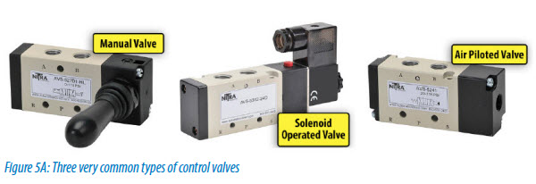
Pneumatic valves, also called directional control valves, are activated in a variety of ways including manually, solenoid operated and air piloted. In their simplest form, 2-way and 3-way valves can be normally open (NO) or normally closed (NC), terms that refer to their normal states without power applied. Another very common valve is a 4-way valve which switches supply and exhaust between two outlet ports.
Manually activated valves are typically switched open and closed by a foot pedal, toggle actuator, handle, knob or push button. An operator controls the activated position of the valve, and a spring or the operator returns the valve to its home position.
Solenoid operated valves use an electrical coil to control the position of a poppet, plunger or spool to open or close a valve. Typical solenoid control voltages are 12VDC, 24 VAC/DC, 120VAC or 240VAC.
Air piloted valves are operated by an external air source such as a solenoid operated valve in a remote location. The valve can also be internally air piloted, enabling use of a smaller integrated electric solenoid to provide an air pilot signal to control the larger valve spool.
Pneumatic Valve Types
With pneumatic valves, the configuration or valve type indicates how air is connected to the device and switched through the valve. This configuration has a strong influence on the device the valve is controlling, and understanding this is critical for specifying the proper valve for the application.
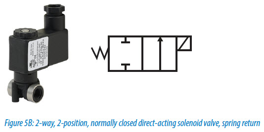
AutomationDirect’s Pneumatic Circuit Symbols Explained article has the information needed to understand valve configurations, but these symbols must be interpreted. The pneumatic symbol for a valve has three parts: actuation (how the valve is actuated), position (the number of positions and ports) and flow (how the air flows through the device). The actuation methods are on the left and right of the symbol, and can be thought of as pushing the boxes left or right. The number of boxes indicates the number of positions, typically two or three. Flow of supply air or exhaust, for each position, is defined by the information in each box.
Each valve position has one or more flow paths, and the arrows in each box represent flow of air and exhaust. The point where each path touches a box is called a port, and to determine the number of ports, one must count a single box of the symbol. The flow path can also be blocked, indicated by a “T” symbol.
Valve Port and Position Types
The number of ports and positions define the type of work a valve is designed for, so selecting these options is a critical design decision. A 2-port or 2-way, 2-position valve has one inlet port and one outlet port. This type of valve is on or off, with no way to vent air pressure, unless that is its only function.
The number of different pathways for air to travel in or out of the valve are referred to as “ways” while the different available states are called “positions”. Valves commonly used in industrial applications are either a 2-, 3- or 4-way configuration, 2- and 3-way valves have 2 positions while 4-way valves can be either 2- or 3-position.
Common pneumatic valve types :
- 2-port (2-way), 2-position
- 3-port (3-way), 2-position
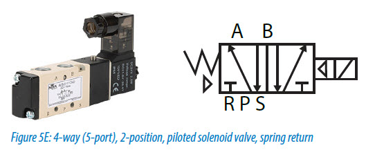
- 5-port (4-way), 2-position
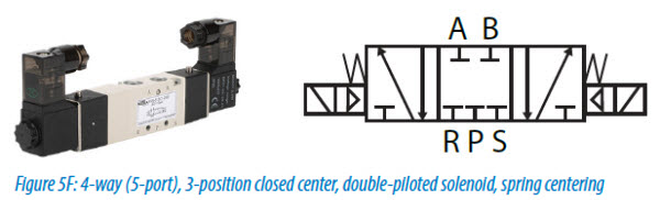
- 5-port (4-way), 3-position
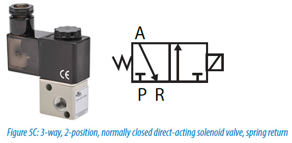
By adding a third port, the 3-port or 3-way, 2-position valve can both supply and exhaust pressure. The three ports are air in, air out and exhaust. While exhausting pressure is important for cylinder movement, this type of valve only works well in applications such as single-acting cylinders with a spring return, or in air blow off applications such as blowing chips in a machining process.
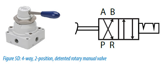
Adding two more ports turns the valve into a 5-port (4-way), 2-position valve. A 5-port valve is technically a 4-way valve since there are two ports open to ‘Exhaust’. This is mainly done to simplify valve construction.
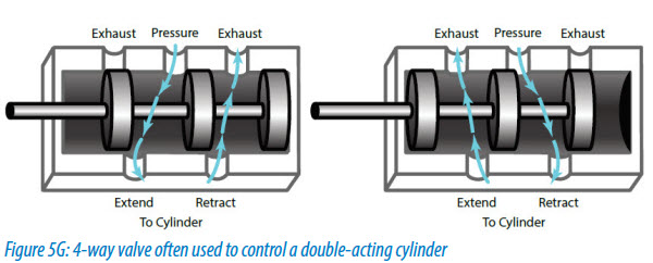
This is the most popular directional control valve because it can extend and retract double-acting cylinders, providing a wide range of control capabilities. This type of valve includes an inlet port, two outlet ports and two exhaust ports. In a 2-position configuration, one output is flowing air from the inlet and the other is flowing air to an exhaust port. When the valve is switched, the two outputs are in opposite modes. This is the most common way to extend and retract a double-acting pneumatic actuator, pressurizing one side of the cylinder while exhausting the other.
Keep in mind that 2-position, single solenoid valves have a spring return. So with an energized valve, if the double-acting cylinder it’s connected to is extending, that cylinder will retract if electrical power is lost (such as when an emergency stop is pressed) but air remains on. If the emergency stop also dumps air pressure in the system, as recommended, the cylinder will retract once pressure is restored unless the valve is re-energized.

If a 2-position, double solenoid valve has a detent feature , the valve spool is held at whichever position it was at the moment the emergency stop was pressed. If the cylinder was at mid-stroke when the emergency stop was pressed, when air is reapplied, the valve will command the cylinder to continue motion to the original energized position, even with both solenoids on the valve de-energized. This motion, due to the maintained valve position, can cause issues. For example, unintended cylinder motion after an emergency stop can damage tooling and should be examined during design.
3-Position Pneumatic Valves
The 5-port or 4-way, 3-postion valve offers a center position that can be specified to either exhaust or block pressure when neither valve solenoid is actuated. These valves are typically used in applications where it is a requirement to stop a cylinder in mid stroke. They are also used to inch or jog a cylinder, or when air must exhaust during an emergency stop and no cylinder movement is allowed after air is reapplied until a reset button or start button is pressed.
Caution is required when using these valves as there is additional control complexity. Center block 3-position valves can trap air and cause unexpected movement under emergency stop conditions, especially if tooling is jammed. To deal with this condition, all energy including trapped air should be removed when an emergency stop is pressed. Air can also leak out, causing the cylinder to drift or drop.
A 3-position center exhaust valve will dump all pressure to a cylinder under emergency stop conditions or when both solenoids are de-energized. During startup, there will be no air to control air flow to the cylinder, causing very fast and possibly damaging cylinder speeds during the first machine cycle. To prevent this condition, both sides of the cylinder must be charged with air pressure at startup.
Valve Form Factor
The form factor of the valve is often driven by its use. This includes both internal configuration and external design. Common internal configurations include poppet, diaphragm and spool. Poppet valves are usually direct solenoid operated, similar to a gate valve in a 2-way, 2-position application. A pilot piston, accessed from a pilot port, moves the valve stem opening the valve. Diaphragm valves work similar to a poppet valve but physically isolate the operator solenoid from the valve and the working fluid by use of the diaphragm. Spool valves, either direct or pilot actuated, are often used on 4-way, 2- and 3-position body ported valves. These spool valves are pistons with seals that when shifted move along a bore opening or closing ports depending on the position. They provide a simplified way to change flow paths, are easy to actuate and are not affected by pressure.
The external form factor of many valves makes them stackable, allowing more valves to fit into a smaller area. Some valves are easier than others to mount individually, and some can be specified to mount either individually or as part of a manifold. Designers may wish to consider compact, modular, manifold-mounted valves in applications with high pneumatic valve counts.
Connecting the Valves
Valves have three primary electrical connection methods: hard wired, modular wired or digital communication. Many valves have a connector built in with removable flying leads, or a DIN style wiring connector.
Modular wiring is typically used with manifold mounted valve configurations. This wiring usually consists of a D-sub connector embedded in the manifold base. This provides an efficient and clean integration option for large pneumatic systems.
EtherNet/IP and other digital communication protocols are becoming a popular way to replace individual discrete wires with a single cable. This is particularly effective when a large number of valves in a small space require activation. This can also reduce cost on the controller side of the system by using a single communication port instead of multiple output modules.
A variety of threaded ports or push-to-connect fittings are also available to attach pneumatic tubing to the valves.
A 5-port (4-way), 2-position valve type is often the best choice for a pneumatic directional control application. Adding a manual operator feature and an indicator light on the electrical connection make maintenance easier, so these options should be considered.
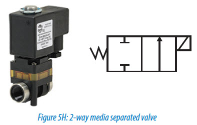
Figure 5H to below is a 2-way media separated diaphragm style valve for use with gases or fluids where the metal working components of the valves do not come into contact with the working fluid. The valve symbol is the same whether it is a poppet, diaphragm or spool valve.
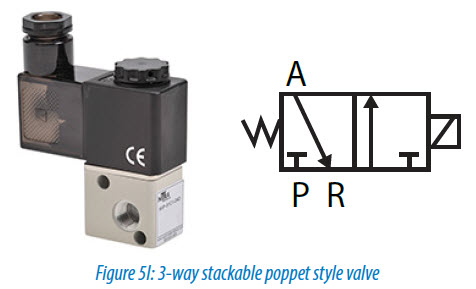
The NITRA™ pneumatic AVP series (Figure 5I) directional control solenoid valve is a 3-way stackable poppet style valve. It provides 2-position, normally closed, spring return operation. The design allows this valve to be stand alone or stacked with multiple valves sharing a common air supply. The valve symbol is the same whether it is a poppet, diaphragm or spool valve.
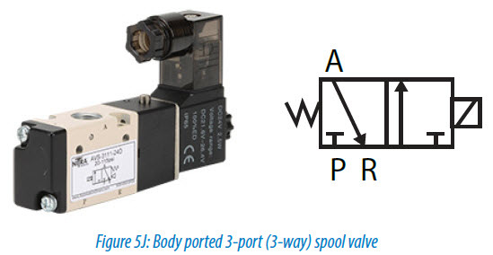
The NITRA™ pneumatic AVS-3 series (Figure 5J) directional control solenoid valves (non-ported meaning the solenoid moves the spool) are body ported 3-port (3-way) spool valves. The single solenoid models provide 2-position, normally closed, spring return operation and the double solenoid models provide 2-position, energize open/energize closed operation.
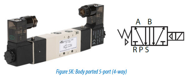
The NITRA™ pneumatic AVS-5 series (Figure 5K) directional control solenoid valves are body ported 5-port (4-way) spool valves. Models are available with single solenoid, spring return or double solenoid 2-position operation. In addition, double solenoid models are available with 3-position, center closed or center exhaust operation. The AVS-5 series can be used in individual valve applications or multiple valves can be field assembled on AM-5 series manifolds simplifying piping connections.
Compact modular valves provide a flexible solution and allow mixing of valve sizes as needed with 3-way/2-position (2 spool valves), 5-way/2-position and 5-way/3-position valves available. Single solenoid spring return or dual solenoids per valve and up to 16 valves (16 solenoids max) per manifold assembly is possible.