In the aerospace industry, any substance that is foreign to the aircraft engine and could potentially cause damage is known as FOD (foreign object debris). FOD costs the industry 4 billion dollars per year on average. Some of the most common causes of FOD damage are the tools required to build or maintain the engine.
Preventing FOD
In order to address this problem, Connecticut-based company HABCO partnered with United Technologies’ Sikorsky Helicopters to design the Pinpoint™ Toolbox that allows mechanics to keep track of their tools at all times. (Figure 1)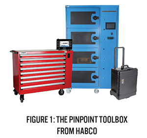
RFID (radio frequency identification) tags are inserted into each tool which allows transmitters in the toolbox to track the tools. If any tools are missing, the toolbox will have a record of what tool was checked out, by whom, and when. This popular system helps the aerospace industry decrease FOD damage caused by misplaced hand tools.
Located in Glastonbury, Connecticut, HABCO has served the Aerospace and Power Generation industries with test and maintenance equipment since 1970. The company has also been involved with the University of Connecticut (UConn) senior design community for several years.
HABCO challenges and mentors a team of students with a real-world design project each year. Many of the resulting student projects are still in use today, both at the HABCO facility and in the field.
This year, HABCO requested the UConn senior design program to help increase their production efficiency by partially automating one of the most time-consuming parts of the Pinpoint™ Toolbox production – the installation of the actual RFID tag into varying sizes of 3/8” drive sockets. (Figure 2)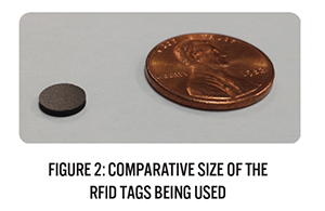
This process consists of removing a pocket of material, roughing the interior surface, inserting the RFID tag and covering the pocket and tag with bonding agent for each of the tools. HABCO requested that the team design and build a simple semi-automated production machine which will be used to cut the RFID tag pockets into the side of the 3/8” drive sockets.
They asked that the machine be small, portable and PLC-controlled. It also had to be user friendly, allowing the operator to simply insert the socket and press ‘go’. Last but not least, they hoped to substantially decrease the time required to prep each socket.
The student team decided to retrofit a manual milling machine, and to design a control system with parts from AutomationDirect.
The entire procedure is now automated using a CLICK® PLC. The socket clamping fixture and the cutting depth adjustment are actuated via NITRA® pneumatic valves and cylinders, while the table bed movement is controlled with a SureServo® servo system. The spindle motor and controller are the only electrical parts remaining from the original milling machine.
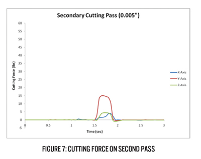
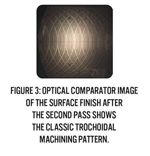 The machine operates using a two-pass side-milling cutting operation. The first cut is the primary cut, removing 0.055” of material at 20 in/min. (Figure 3) The primary cut leaves a very smooth, almost mirror finish that is actually too smooth for effective bonding of the ID tag. The team proposed a second, faster pass to rough up the surface. The secondary cutting pass removes 0.005” of material at 100 in/min. The automated second pass produces a rougher surface finish, and allows for more successful adhesion of the bonding agent than HABCO’s previous method of using a rotary cutting tool to manually rough the pocket. (Figure 4)
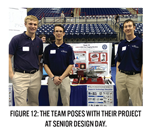
The student team consists of three senior mechanical engineering students at the University of Connecticut: Andrew Chuckta, Ryan Mannix, and Joseph Joaquim.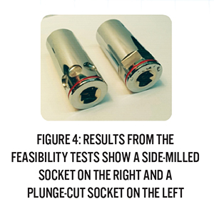
Andrew explained some of the challenges the team faced with the research leading up to their final design.
“We performed feasibility tests using a milling machine at UConn where we compared the use of a plunge-cut ‘bore’ versus a side-milled ‘slot’; we experimented with the use of 2-flute versus 4-flute cutting tools. The 4-flute outperformed the 2-flute regardless of the type of cut, and milling the side slot turned out to be much less detrimental to the cutting tool.”
He reports that they could only prepare 2-3 sockets using the plunge cuts before having to replace the tool, but that the same type of tool was capable of completing at least 25 sockets using the side-cutting method.
An additional concern that actually proved trivial related to the chrome plating on the surface of the sockets. Based on their knowledge of the extreme hardness of chrome plating, they performed several “Rockwell C” hardness tests to investigate concerns they had concerning the material’s density.
They discovered that because the coating is so thin on the sockets, it wasn’t actually a problem when it came to cutting them. The team concluded that while the chrome plating is quite hard, in this application, it is more for improving wear and abrasion resistance, reducing friction, and preventing seizing and galling of the socket under normal operation. Therefore, the team agreed that it would not impact their ability to machine the sockets.
The students also arranged to use a large, general purpose CNC machining center for a cutting test in order to determine the forces applied to the socket during both cutting passes.
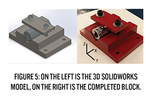 The team designed a “V-block” fixture in Solidworks to mount a sample socket to a force transducer, acquired the materials, and machined the fixture. After some cleanup and a quick coat of ‘HABCO red’, they were ready to test the cutting force. (Figure 5)
A LabView model was used to record the forces in the x, y and z axes. The ProtoTrak control on the CNC mill was set to perform the primary cutting pass and secondary roughing cutting pass. Data from the cutting test allowed the team to design a socket fixture with enough clamping force to secure the sockets in their portable mill. The forces recorded during the test are shown below. (Figures 6 & 7)[hozbreak] 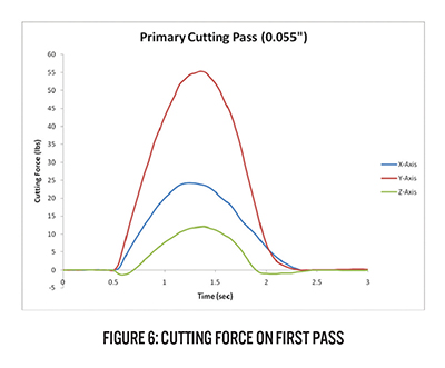
 [hozbreak]One goal of the project was to repurpose as much of the original mill as possible. The spindle and spindle speed controls were not modified as this would have added an unneeded complication to the electrical system. The rest of the machine would be modified to work where possible.
A multitude of configurations and placements of the spindle motor were evaluated before it was decided the spindle motor would lie on its back. This placement allowed an efficient form of adjustment for the depth of cut, and it allowed more mechanical pieces of the original mill to be reused.
Once orientation of the spindle was chosen, the kinematics of the machine and how it would operate were quickly determined.
The team realized that a secondary axis of motion control would not be necessary and that the 0.005” of an inch change in cutting depth could be accomplished with a double-acting air cylinder. Primary axis (bed) movement was designated to be controlled by a 750W SureServo® servo motor. The servo motor is attached to the mill bed via a timing belt, providing ample torque to drive the bed during the milling operation. The built-in indexer in the SureServo amplifier stores the separate back and forth move parameters, and discrete output signals from the CLICK are used to initiate the various moves.
In order to have the same depth of cut regardless of the diameter of the socket, one edge of each socket needed to locate consistently. A large ‘stop plate’ with a slot was determined to be the best option. The end mill protrudes through the slot and the moving bed of the mill allows for translation across the socket face, making the cut.
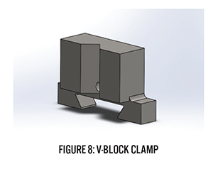
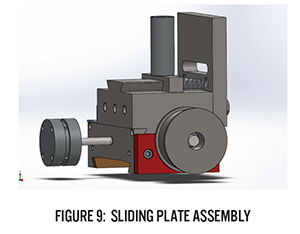
A “V-block clamp” was designed to keep the socket pressed against the stop plate during the cutting process. (Figures 8 & 9)The V-block dimensions were designed to accommodate all the various socket sizes. The required clamping force is provided by a second NITRA pneumatic cylinder which presses against the back of the V-block, holding the socket firmly against the stop plate.
Because the student team consisted of three mechanical engineers with limited electrical experience, several hours were spent meeting with HABCO’s Senior Electrical Engineer Peter Brini throughout the design of the electrical subsystem.
Brini helped them design a schematic diagram detailing the entire electrical operation of the machine. Power is distributed to the mill spindle, table drive motor, limit switches, user controls, solenoids, and the PLC.
The machine is designed to have all the electrical and pneumatic components located in, or on, a Hubbell/Wiegmann NEMA 12 enclosure. The enclosure is powered by 120VAC combined with a compressed air line to help make the machine truly portable.
The original electrical design was based on using a standard 1HP AC brushless motor with a variable frequency drive to control the speed and movement of the mill table. The team soon discovered that this motor was too large to fit the small mill.
They changed the design to use a 750w SureServo servo system. Smaller in size than the AC motor, the servo motor has more power at a lower RPM, lower inertia, and provides encoder feedback to the drive. It also allows the machine to have much more accurate table movement. (Figures 10 & 11)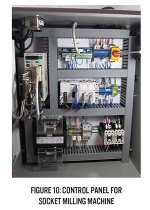
Peter Brini attended the design presentation at Senior Design Day on the UConn campus, in May. Pleased with the students’ work, he said, “The machine meets all of our requirements. It’s table-top sized, automated, and produces a consistent roughened slot on any size 3/8″ socket.”
He also pointed out that production time was decreased from two cuts per minute, with additional processing required, to over seven sockets per minute with no post-process roughening required.[hozbreak]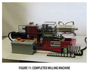
 Brini concluded, “HABCO is very happy with the project results, and we will be using the machine to cut all the sockets for our Pinpoint Toolbox product line.”
HABCO also seems quite pleased with at least one member of the student team, as they plan to hire Joe Joaquim now that the senior project is complete and all three students have graduated with mechanical engineering degrees.
To read more articles about motion control, click here.
By, Chip McDaniel

Originally Posted: Sept. 10, 2014