The purpose of the National Electrical Code® (NEC®) is the practical safeguarding of persons and property from hazards caused by using electricity.
The NEC is prepared by a committee made up of a Technical Correlating Committee and 19 code-making panels.
The committee’s responsibility is to create documents specifying code, which when adhered to, minimizes the risks of electricity as a source of electric shock and as a potential ignition source for fires and explosions.
Published by the National Fire Protection Association, the NEC is updated every three years. Significant changes in the 2005 edition that we will be discussing are the new Article 409 and changes made to existing Article 430.
Article 409
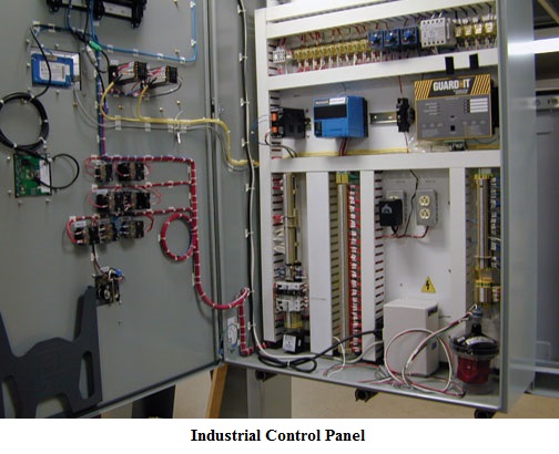
Article 409 covers industrial control panels intended for general use and operating at 600V or less. A fine-print note references Underwriters Laboratories (UL) 508A as the safety standard for industrial control panels. Extensive substantiation was provided with the proposal for each of the new requirements. While the title of the article is Industrial Control Panels, the scope indicates the article applies to “… panels intended for general use.”
The new article is not limited to industrial occupancies but rather, has general application. The term “Industrial Control Panel” is defined in Section 409.2 as “an assembly of a systematic and standard arrangement of two or more components such as motor controllers, overload relays, fused disconnect switches, circuit breakers and related control devices such as pushbutton stations, selector switches, timers, switches, control relays, and the like with associated wiring, terminal blocks, pilot lights, and similar components. The industrial control panel does not include the controlled equipment.”
It should be noted that UL and other electrical testing laboratories have a procedure whereby a “panel shop” can produce control panels that comply with the UL Industrial Control Panel safety standard. As such, the control panels are eligible to bear the listing mark of the electrical testing laboratory. The internal wiring of these listed control panels is not usually inspected by the local electrical inspector at the time of installation, as provided in Section 90.7 of the NEC. On the other hand, the internal wiring of industrial control panels that are built in accordance with new NEC Article 409 is usually subject to inspection by the local Authority Having Jurisdiction (AHJ). This is due to the field-assembled control panels not being listed by a qualified electrical testing laboratory, but being assembled in accordance with NEC rules.
If the AHJ determines the control equipment being field-assembled is an Industrial Control Panel, compliance with all conditions of Article 409 is required, including the extensive marking specification in 409.110. The NEC offers no explanation for the term “systematic and standard arrangement of two or more components” as included in the definition in 409.2. The question is raised since industrial control panels are often one-of-a-kind, designed to control a specific operation rather than being mass-produced.
Rules are provided in 409.20 on sizing a supply conductor to the industrial control panel. These conductors will often meet the definition of a “feeder conductor” in the NEC Article 100. In this application, a feeder conductor is a set of conductors that usually has overcurrent protection on the supply side and terminates at equipment where branch circuits originate. The supply conductors to the industrial control equipment must be no smaller than 125 percent of the full-load current rating of all resistance heating loads, plus 125 percent of the full-load current rating of the largest motor, plus the full-load current of all other motors and apparatus supplied. An adjustment can be made based on the duty cycle of the equipment. See 430.22(E) for the application of multipliers for motors that operate under a duty-cycle concept.
Overcurrent protection of field-assembled industrial control panels must comply with the requirements of Article 240, Parts I, II and IX. Part I includes the general rules for overcurrent
protection, Part II provides requirements on the location of overcurrent protection, and Part IX provides rules on overcurrent protection for over 600V nominal.
Disconnecting means for industrial control panels that supply motor loads must meet rules for disconnecting motor controllers in Article 430, Part IX. This generally requires a disconnecting means on the supply side of the controller and within sight of the controller (defined in Article 100 as visible from and not more than 50 feet away).
Requirements for grounding industrial control panels must generally comply with Article 250. Specific requirements are provided in 409.60.
Construction requirements for industrial control panels are found in Part III of Article 409. Rules are provided for enclosures, installing busbars and conductors, wiring space, and for where the control panel can be used as service-entrance equipment. Extensive marking requirements are contained in 409.110, including the short-circuit current rating of the assembly. A fine-print note refers to UL 508A-2001, where an approved method for determining the short-circuit current rating can be found.
Rules in other standards might apply to specific control panels such as NFPA 79 for industrial machinery.
Article 430
Several changes to Article 430 were made for the 2005 NEC. This includes some reorganization, renumbering, and inclusion of a new Part X on adjustable speed drives.
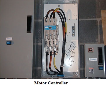
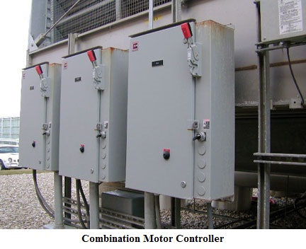
Section 430.8 covers marking on motor controllers. Motor controllers are now required to be marked with the “short-circuit current rating.” Exceptions are provided for certain motor controller applications. The short-circuit current rating is the current the contactor is rated to open under short-circuit conditions. A controller must be selected that has a short-circuit rating that equals or exceeds the short-circuit current available at its line or supply terminals. Motor controllers are provided to start and stop the motor. Branch-circuit, short-circuit and ground-fault protection is provided on the line side of the motor controller by a circuit breaker or fuse. The newly required short-circuit marking can be thought of as a withstand rating.
The concept is that the motor controller will remain intact while carrying short-circuit current until the circuit breaker or fuse on the line side opens the circuit. The product safety standard for industrial control equipment,
UL 508A-2001, Supplement SB, provides an example of an approved method for determining the short-circuit current rating.
Other markings required on the controller include the manufacture’s name or identification, the voltage, the current or horsepower, and other necessary data to properly indicate the applications for which the controller is suitable.
Four exceptions were added to exempt the short-circuit current rating marking. Exception No. 1 exempts certain controllers for small motors as allowed in Part VII, such as clock motors, attachment plugs and receptacles, and snap switches. The second exception permits controller short-circuit current ratings to be marked elsewhere on the assembly. The third exception covers applications where the short-circuit current rating is marked on the assembly in which the controller is installed. Exception No. 4 exempts controllers rated less than 2 hp at 300V that are listed exclusively for general-purpose branch circuits.
Section 430.32(A) covers continuous-duty motors, more than one horsepower. The wording in this section indicated motors used in a continuous-duty application required overload protection; continuous-duty motors used in non-continuous applications did not.
A change was made since the previous wording could have led individuals to think motors are rated as continuous-duty. The duty of a motor is determined by the motor’s application and defined in Article 100 under duty. A motor rated by the manufacturer as continuous and used as other than continuous-duty requires no overloads.
Section 430.102(B) provides the location requirements for the disconnecting means for motors. This section has been the subject of much discussion over recent NEC editions. Changes were made to the rule on disconnecting means being located within sight of the motor and driven machinery. The second sentence of (B) in the 2002 NEC requirement is deleted, and a phrase in the exception has also been deleted.
The NEC Code Panel made organizational and substantive changes to the main text and exception. The second sentence of the opening paragraph is moved to follow the fine-print notes, so the exception does not now modify the previous second sentence. Now, clearly, the disconnecting means on the supply side of the motor controller is permitted to be the only disconnecting means for the controller and motor if it is within sight of both.
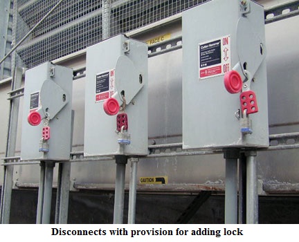
The Code Panel stated the word “permanently” in the exception, as related to the method for locking the disconnecting means. It was deleted because it was considered confusing. The intent of this change in the 2002 NEC was to require the provisions for locking always to be in place and not to be removed when the lock is removed. “Permanently” was used to convey this concept but some interpretations have been that “permanently” means it shall not be possible to remove the locking means. As sited in the NFPA documents, “That was not the intent and there are few, if any, locking means that are permanent to the point they cannot be removed.” The original purpose of adding “permanently” to the Code was to require that a locking means be available at all times, i.e., to prohibit a portable locking means that is removed when the lock is removed.
Section 430.109(A)(6) covers manual motor controllers. Manual motor controllers are often a switch that includes a heater element to provide motor overload protection. Manual motor controllers are permitted as the motor disconnecting means where marked by the manufacturer as being suitable for that purpose. Rules were added on locating the manual motor starter on the line side of the fuses used for running overload protection as permitted in 430.52(C)(5).
Semiconductor fuses are permitted to be used as branch-circuit fuses under 430.52(C)(5). However, they are often used as supplementary fuses to protect electronic equipment, and may be located on the load side of listed manual motor controllers marked as “Suitable for Motor Disconnect.” Since, as branch-circuit fuses, they are technically the final motor branch-circuit protective device, their use downstream from the manual motor controllers violates the Code. The change permits the use of these fuses in this location, as supplementary protective devices. The manual motor controllers additionally marked “Suitable as Motor Disconnect” will be suitably protected by the branch-circuit protective devices located on their line side.
Section 430.109(A)(7) lists rules for installing system isolation equipment. “System Isolation Equipment” is defined in Section 430.2 as “a redundantly monitored, remotely operated contactor-isolating system, packaged to provide the disconnection/isolation function, capable of verifiable operation from multiple remote locations by means of lockout switches, each having the capability of being padlocked in the OFF (open) position.” The concept of system isolation equipment provides lockout capabilities in the motor control circuit rather than in the power circuit.
This change to Article 430 was intended to align with the latest edition of NFPA 79, the Standard for Industrial Machinery. Specifically, it refers to Section 5.5, Devices for Disconnecting (Isolating) Electrical Equipment, paragraph 5.54(3). This type of equipment is principally intended for industrial machines covered by NFPA 79, where, because of multiple entry points or high-frequency usage, the use of other isolation devices becomes impracticable.
Because of size, manufacturing machines often have several entry points used by operators and maintenance personnel who cannot always see one another. With a monitored safety lockout system, each point of entry has a lockout capable disconnecting means, and a method to verify to the user that the disconnection function has succeeded. Each of the several point-of-entry “disconnecting means” is monitored and opens a magnetic contactor that prevents the mass-production industrial machine from being energized.
The “redundantly monitored, remotely operated contactor isolating system” is always located within the machine’s electrical system on the load side of a circuit breaker or fuse. A typical redundantly monitored, remotely operated, contactor isolating system that incorporates control lockout provisions has been reviewed with OSHA; the resultant interpretation is that it can be part of an energy control program and therein a suitable disconnecting means for such purposes.
Underwriters Laboratories is expected to develop one or more product safety standards for a redundantly monitored, remotely operated contactor isolating system that incorporates control lockout provisions.
The new Part X of Article 430 covers adjustable-speed drives. New definitions have been added to 430.2 for “adjustable-speed drive” and “adjustable-speed drive system.” This recommended change places requirements for these drive systems in a central location in Article 430 that begins at 430.120.
The following list provides an indication of the subjects covered in the new part of Article 430.
- X – Adjustable Speed Drive Systems
- 430.120 General
- 430.122 Conductors – Minimum Size and Ampacity
- (A) Branch / Feeder Circuit Conductors
- (B) Bypass Device
- 430.124 Overload Protection
- (A) Included in Power Conversion Equipment
- (B) Bypass Circuits
- (C) Multiple Motor Applications
- 430.126 Motor Overtemperature Protection
- (A) General
- (B) Motors with Cooling Systems
- (C) Multiple Motor Applications
- (D) Automatic Restarting and Orderly Shutdown
- 430.128 Disconnecting Means
Adjustable Speed Drives
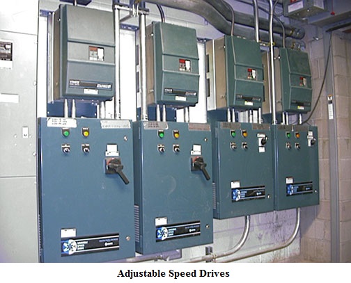
The substantiation for the proposal stated adjustable-speed drive systems has gained enormous popularity over the last few years, but appropriate installation rules need to be addressed. A companion proposal was accepted to add definitions to Section 430.2 of two terms pertaining to drive systems.
As a result of this new part of Article 430, previous parts were renumbered as were several sections and tables that follow new Part X. Part XIV now covers motor full-load current tables and begins with Table 430.247, rather than Table 430.147.
Conclusion
While we have reviewed the most significant changes made to Article 430 and new Article 409, several hundred additional changes were made in the new 2005 NEC. Obviously, some changes are more significant than others. In addition, NFPA has published a schedule to produce the 2008 NEC. The schedule shows a closing date of Nov. 4, 2005 for receipt of proposals to change the 2005 NEC.
By Phil Simmons,
Guest Writer
About the Author
Phil is self-employed as Simmons Electrical Services. Services include consulting on the National Electrical Code and other Codes; writing, editing, illustrating and producing technical publications and training materials; presenting at technical seminars, and other training sessions and inspection of complex electrical installations. He also provides plan review of electrical construction documents.
Phil presently serves NFPA on Code Making Panel-5 of the National Electrical Code Committee (grounding and bonding). He previously served on the NEC CMP-1 (Articles 90, 100 and 110), as Chair of CMP-19 (articles on agricultural buildings and mobile and manufactured buildings) and member of CMP-17 (health care facilities). He served six years on the NFPA Standards Council, as NFPA Electrical Section President and on the NEC Technical Correlating Committee.
Originally Published: Sept. 1, 2005


