No single discovery has affected our lives, our culture and our survival more than electricity. Electricity is everywhere; it lights our way, cooks our food and can even brush your teeth. For an example, imagine where the medical field would be without electricity and in that sense how many lives have been saved due to electrical devices like defibrillators, pacemakers, etc. From talkies to eight tracks to screaming “I want my MTV”, even hashtagging, none of it would be possible #WithoutElectricity. Read on to discover more about basic electrical theory.
What is Electricity?
So what is electricity and where does it come from? More importantly, why is carpet, socks and a doorknob a bad combination? In its simplest terms, electricity is the movement of charge, which is considered by convention to be, from positive to negative. No matter how the charge is created, chemically (like in batteries) or physically (friction from socks and carpet), the movement of the discharge is electricity.
Understanding Current
This flow of electrical charge is referred to as electric current. There are two types of current, direct current (DC) and alternating current (AC). DC is current that flows in one direction with a constant voltage polarity while AC is current that changes direction periodically along with its voltage polarity. Thomas Edison and Alessandro Volta were pioneers in DC current and wrote much of electricity’s history. But as societies grew the use of DC over long transmission distances became too inefficient. Nikola Tesla changed all that with the invention of alternating current electrical systems. With AC it is possible to produce the high voltages needed for long transmissions. Therefore today, most portable devices use DC power while power plants produce AC. 
Ohms Law
The most fundamental law in electricity is Ohm’s law or V=IR. The V is for voltage, which means the potential difference between two charges. In other words, it is a measurement of the work required to move a unit charge between two points. When we see a value such as 10 Volts, it is a measurement of the potential difference between two reference points. Normally the two points will be +10V and 0V (also known as ground), but it can also be the difference between +5V and -5V, +20V and +10V, etc. In the field, you might hear the term “common grounds” which refers to each device in a system using the same zero-point reference (or ground) to ensure the same potential difference ( or voltage) is applied throughout the system. The next component of Ohm’s law is current, the units of which are Amperes; in the formula, current is represented by the very logical choice of the letter I. As mentioned previously, current is the measurement of the flow of charge in a circuit. This leaves us with the letter R which represents Resistance. Electrical resistance, measured in Ohms, is the measure of the amount of current repulsion in a circuit. Simply, resistance resists current flow. When electrons flow against the opposition offered by resistance in the circuit, friction occurs and heat is produced. The most common application for resistance in a circuit is the light bulb. The light bulb introduces enough resistance in a circuit to heat up the filament inside, causing light to be emitted. Resistance in a circuit can also be helpful when needing to alter voltage levels, current paths, etc. Resistors are self-contained packages of resistance that can be added to a circuit and are commonly used to divide voltage levels.

Series and Parallel Circuits
Before I get into the use of Ohm’s law, I want to introduce a few other circuitry concepts. First, we need to understand what Series and Parallel circuits mean. Series circuits are those which are connected in-line with the power source. The current in series circuits is constant throughout but the voltage may vary. Parallel circuits are those which branch off from the power supply. The total current supplied from the power source is divided among each of the branches but voltage is common throughout. 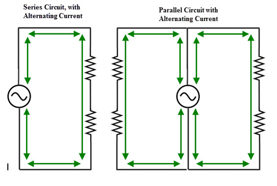 You have probably experienced the pain involved with installing Christmas lights only to realize none of them work. Cue Clark Griswold! There is probably one bulb out somewhere in the hundreds that you hung up. More than likely it is because one of the lights decided to break or burn out and because they are wired in series the rest are now out as well. Since all of the lights are in-line with each other, if one goes out it causes an open circuit at that point. No current will flow to the other lights because of the open circuit path.
 Fortunately, a lot of the new light strands are wired in parallel. Therefore if one light goes out, then only that branch of the circuit will be out. The open will be isolated to that branch and current will continue to the other lights in the strand, Joy…to… the…World!
Applying Ohm’s Law
Now, let’s apply Ohm’s law to the following circuit (for exercise purposes only, circuits are theoretical) and calculate the voltage and current supplied to each load. The schematic below shows a supply circuit for a child’s bedtime toy. R1 represents the resistance value of the speaker and R2 shows the resistance value of the LEDs. R1 is equal to 430 Ohms, R2 is equal to 284 Ohms and the supply is a battery with 5VDC and 5A. What is the voltage supplied to the LEDs and to the speaker? First, we need to find the current in the loop once the belly is pressed and switch 1 (S1) closes. The supply offers 5 amps of current but the circuit will only use what is demanded by the loads. Using Ohm’s law, we can reconfigure the formula to solve for current in the loop, or I (loop) = V (loop)/ R (loop). Using the supplied values, we can calculate that I (loop current) = 5VDC/714Ω = 7mA.
Ohm’s Law Applied to a Series Circuit
So now that we know the current in the loop is 7mA and in a series circuit that current is constant throughout, we can use Ohm’s law to calculate the voltage supplied to the speaker: V(speaker) = I(loop) x R(speaker) or V(speaker) = (7mA) x (430Ω) or ~ 3VDC. The LEDs will in turn have a supply voltage of: V(LED) = (7mA) x (284) or ~ 2VDC. This circuit is known as a voltage divider circuit. The supply voltage was divided among the loads in proportion to the resistance each load carries. R1 had a higher resistance and received 3VDC of the total 5VDC supply and R2 received the rest or 2VDC. It can otherwise be stated that R1 has a voltage drop of 3VDC and R2 has a voltage drop of 2VDC. 
Kirchoff’s Voltage Law (KVL)
This voltage drop principle leads to another important law in basic electrical engineering, Kirchoff’s Voltage Law (KVL). This law states that the algebraic sum of the voltages in a closed loop is always equal to zero. If we only knew the supply potential and the voltage drop of R1, we could use KVL to find the other voltage drop. With KVL you have to follow the current path and use the polarities of the components shown. If current path is unknown you have to assume one. We will use the positive to negative (clockwise) path. V(supply) + V(1) + V(2) = 0 or -5VDC + (+3VDC) + (+V(2)). Solving for V(2), V(2) = 2VDC, which we know to be correct. KVL really comes in handy when there are multiple supplies in a loop or multiple loops.
Ohm’s Law Applied to a Parallel Circuit
Now let’s take the same toy and rewire it so that the speaker and LEDs are in parallel with the power source, as seen below.  Let’s also use the same values as before with R1 = 430Ω, R2 = 284Ω, V(source) = 5VDC, I(source) = 5A. This time let’s find out how much current each branch is pulling from the source. As mentioned previously, with parallel circuits the voltage across each branch will be equal to the supply voltage. So right away, I can tell you that the voltages across R1 and R2 are both 5VDC. Using Ohm’s law, I can also calculate the current in each loop or branch. Set up the formula for current or I(R1) = V(R1)/R1 which is solved to be, I(R1) = 5VDC/430Ω = 11.63mA. Doing the same for the other loop, we get I(R2) = V(R2)/R2 , I(R2) = 5VDC/284Ω = 17.6mA. Let’s also find the total current draw by the whole circuit. No, we’re not going to add the two branch currents together (smart, but too easy); we’ll use Ohm’s law and the parallel resistance calculation. First we need to find the total resistance in the circuit. In series circuits we would just add all of the resistance values together. In parallel, you have to add the reciprocals of all the resistance values together and then reciprocate back. Here we go, 1/R(total) = 1/R1 + 1/R2 = 1/430Ω + 1/284Ω = 0.0058467… Now reciprocate back to get R(total) = 171Ω. Using this value we can now find I(total) = V(total)/R(total) = 5VDC/171Ω = 29.23mA. You can see that if we had added the two loop currents together we would have gotten the same result, I(R1) + I(R2) = 11.63mA + 17.6mA = 29.23mA. High fives all around! One quick note, current will always try to take the path of least resistance. I was taught to think that current flows much the same as water. If you have two channels in a river and one is partially blocked by logs, then most of the water will flow through the clear channel. Same is true with current. In a parallel circuit, the branch with the least amount of blockage or resistance will receive the majority of the current. In our example both channels are partially blocked but the one that is most clear (R2) will receive the most current. Pop Quiz, what if R2 was to short out? Well, in a short there is no resistance, so all of the current would flow though that branch. The wire could overheat causing the worm to lose its glow and quite possibly everything else. Fusing that branch would save little Suzie’s favorite toy and fusing is a very important part of design both in circuits and in systems as a whole.
Kirchoff’s Current Law (KCL)
Time for a little recap: in series circuits, current is constant and voltage varies but in parallel circuits voltage is constant and current varies. This current varying in parallel circuits brought about Kirchoff’s next big law in basic electrical engineering, Kirchoff’s Current Law (KCL). This law basically states that current into a node will equal the current out of the node. In other words, the net current in a node is zero or 0 = I(in) – I(out). Looking at the node (connection between two loops) in the diagram below, we already know that to be true: 0 = 29.23mA – (11.63mA + 17.6mA).  KVL and KCL are very useful in more advanced circuitry like the one below (toy car remote control).
 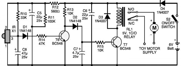 [hozbreak]
Power Equation
One last equation that is useful to remember is the power equation, P = IE. P is for power measured in Watts, I is for current and the E is for voltage. This equation can be combined with Ohm’s law to solve for values that are unknown. For example: In Ohms law we know that I = E/R so combined with the power equation (P = IE) we get P = E (E/R) or P = E^2/R. Also, from Ohm’s we know that E = IR, so combine this with P = IE and we get P = I^2R. Using the previous parallel example, we can find the power consumed by the circuit. We know the voltage rating of the battery is 5VDC and we calculated the total resistance in the parallel circuit (171Ω). Using these two values, the power consumed by the toy would be: P(total) = (5VDC)^2/171Ω = 146mW. [hozbreak]
Conclusion
I hope this information helps to refresh that which may have been forgotten. It is in no way intended to encompass every possible scenario, equation or topic that is electricity or electrical circuits. To help further understand the ins and outs of electricity and electrical principles, search the plethora of electrical engineering books available online. One of the big industries spawned from electrical principles is automation. Automation is electricity working for you to accomplish a task. Further information on automation and how to apply it can be found in our eBook: Automation 101: An Industry Guide to Control System Engineering. For additional information on electrical engineering, please go to any of the following sources: IEEE, ISA, and Electrical Codes.