AC motors are electric motors driven by alternating current (AC). AC motors are widely used in industry, primarily due to their high efficiency, and their ability to produce constant torque up to the rated speed.
AC Motor Types
The two most widely used types of AC motors are induction motors and synchronous motors.
How AC Motors Work
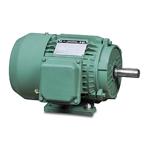
The two basic parts of an AC motor are the stator (the stationary outer drum) and the rotor; the rotating inner portion of the motor which is attached to (and drives) the motor shaft. Both the stator and the rotor produce rotating magnetic fields. In the windings of the stator, this rotating field is provided inherently by the sinusoidal nature of alternating current. In the rotor, the magnetic field is created by permanent magnets, reluctance saliency, or by additional electrical windings.
Synchronous motors operate in lock step with the frequency of the supply current because their rotors have either permanent magnets or electromagnets generating the rotating electromagnetic field.
In an induction motor, the magnetic field in the windings of the rotor is ‘induced’ by the magnetic field of the stator. In order for this induction to produce torque, the speed of the rotor’s field must lag the field of the stator’s magnetic field. This speed differential is known as “slip”, and is the reason that induction motors will have a “nameplate RPM” rating that is about 5% less than their synchronous speed. For example, an Ironhorse model MTRP-001-3DB18 (1hp, three phase, four pole, AC induction motor) has a synchronous speed rating of 1800 RPM (assuming 60hz power), but the “Nameplate RPM” rating is 1760. This motor shaft will turn at 1760 RPM when powered “across the line” with the US standard of 60 Hz three-phase power.
Differences to DC Motors
Industrial DC motors have historically been of the brush type. DC motors with brushes and commutators have a number of drawbacks when compared to AC motors: added maintenance (brush replacement), limited speed ranges and overall life expectancy is shorter. AC induction motors have no brushes and have a much longer life expectancy.
DC motor speed is controlled by varying the armature current, while AC motor speed control is achieved by varying the frequency of the alternating current, often with a variable frequency drive(VFD).
Brushless DC motors have become available over the last several decades, primarily as a result of the advent of the semiconductor control circuitry required to operate them, and the availability of high-quality permanent magnets. Brushless DC motors require no brushes or physical commutator and thus have increased service life. They also overcome the speed limitations of the brushed versions.
AC Motor Control
When simple on/off control is required, contactors or manual motor starters are often employed. Contactors (large, three-phase relays) allow a PLC or other controller to toggle power to an AC motor. Reversing motor starters are specialized versions with two contactors wired such that they also allow reversing of the direction of spin of the motor shaft. Manual motor starters include a manually operated knob that allows the operator to switch the power. All of these types are known as “across-the-line” control – as the motor is wired directly to the incoming power “line” (through the contactor or motor starter).
Soft Starters
Soft starters are more complex motor controls that enable acceleration and deceleration ramps for stopping and starting the motors more smoothly than is possible with across-the-line control. Soft-starters typically use silicon control rectifiers (SCR control) to gradually increase or decrease the firing angle to slowly increase or decrease the amount of energy used, and give the application a softer start or ramp down than an across-the-line motor starter. Soft starters reduce wear and tear on the motor and any connected mechanical devices, and they also drastically decrease the in-rush current required to start the motor. For large motors, this can have major implications for reducing utility costs.
Speed Control (VFDs)
Three-phase AC induction motors are sometimes powered by Variable Frequency Drives (VFDs) which, as their name suggests, vary the frequency of the power to the motor in order to vary the speed of the motor. These devices accept standard 60hz input power (single- or three-phase), rectify it to DC, and then use pulse width modulation (PWM) to create simulated AC power at whatever frequency is required to spin the motor at the target speed. More about VFDs here.
Single-Phase Operation
Single-phase AC induction motors are also available. These motors require special circuitry to start (starting capacitors, and centrifugal switches) but operate identically to their three-phase counterparts once they are spinning. Single-phase AC induction motors are not compatible with VFDs, and can result in higher utility costs due to their inherently unbalanced load on the power grid.
How to Specify AC Motors
If you are specifying a motor for a new application – start by determining the voltage, speed and horsepower required along with the application type as detailed in this article.
If you are replacing a properly-sized motor in an existing application, you can find all the required information on the motor nameplate of the existing motor. See this White Paper, Important Considerations for Replacing and Sizing AC Motors to learn how to determine whether to rewind or replace a motor and how to find the right motor size for your application.
In addition to the standard specifications for motor speed, horsepower, and operating voltage, designers should also consider NEMA design (speed-torque-slip relationship), enclosure type and cooling provisions (if any), frame size, and mounting options. Here are some guidelines:
NEMA Design Classifications
There are four different NEMA design classifications for speed, torque, and slip that help determine suitability for various applications:
- NEMA design A; suitable for a broad variety of applications – such as fans and pumps. Motors have maximum 5% slip, high to medium starting current, normal locked rotor torque, and normal breakdown torque.
- NEMA design B; intended for a broad variety of applications with normal starting torque (fans, blowers and pumps). Motors have maximum 5% slip, low starting current, high locked rotor torque, and normal breakdown torque.
- NEMA design C; intended for equipment with high inertia starts – like positive displacement pumps. Motors have maximum 5% slip, low starting current, high locked rotor torque, and normal breakdown torque.
- NEMA design D; intended for equipment with very high inertia starts (cranes, hoists etc.). Motors have maximum 5-13% slip, low starting current, and very high locked rotor torque.
Enclosure Type and Cooling
Common enclosure types include Drip Proof (DP), Totally Enclosed Fan Cooled (TEFC), and Totally Enclosed Non-Ventilated (TENV).
- Drip Proof motors are open frame motors intended for indoor applications in clean environments. Ventilation openings are designed to prevent ingress from falling solids and liquids.
- TEFC motors have a fan attached to the rear of the motor shaft to help cool the motor. While there are no ventilation openings in the motor housing the enclosure is not air or liquid tight. While a TEFC motor may be able to operate at a higher ambient temperature – be careful at low speeds (under VFD control) as the cooling fan is attached to the motor shaft, and may need certain minimum speed to effectively cool the motor.
- TENV motors are also non-ventalated, but the enclosure is not air or liquid tight.
Additional classifications include Washdown rated motors (TEWD), explosion proof motors (XPRF), and motors designed for hazardous locations (HAZ).
Frame Size and Mounting
Most AC motors today are built to specific NEMA sizes. In small horsepower ranges many motors are available in a “NEMA 56C” frame size. The “56” refers to the motor frame dimensions The “C” indicates a “C” face (flange) mountable motor. This is the most popular type of face mounted motor and has a specific bolt pattern on the shaft end to allow mounting. The critical dimensions on “C” face motors are the bolt circle, register diameter, and the shaft size. C flange motors always have threaded mounting holes in the face of the motor. Many motors are offered with both C-Face mounting options and a rigid or removable mounting base. As horsepowers increase – a number of different “T” frame designations are used to denote the standard NEMA sizes.
To VFD or Not to VFD
If you are planning to use the AC induction motor with a Variable Frequency Drive(VFD) – there are a number of additional considerations, check out our article To VFD or Not to VFD.
For additional information on specifying and sizing motors of all types – please click here.