When used in electrical power and control circuits, relays allow lower power circuits to operate higher power circuits, while providing isolation.
Relay Definition
Relays are a fundamental device for switching an electrical circuit on or off, much like a toggle switch or a limit switch. But a relay is operated based on an electrical control signal, as opposed to a toggle switch that is operated by a human hand, or a limit switch triggered by equipment contact. This blog post covers why relays are used, how they work, the terminology involved, some various relay features and where relays are used.
Why are Relays Used?
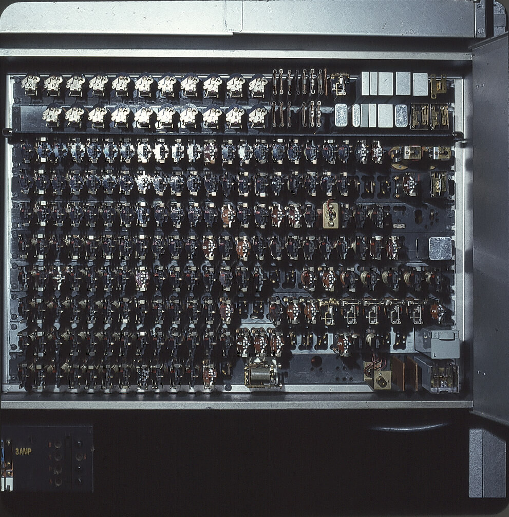
Photo Credit: https://commons.wikimedia.org/wiki/File:Panel_Sender_Relays.jpg
The main reason for using relays is so that separate circuits, often operating at higher voltages and currents, can be switched on and off by much lower power control circuits, such as the digital outputs (DOs) of a programmable logic controller (PLC). Small on/off control circuits are effectively amplified to operate large on/off power circuits (Figure 1). The control circuit and the power circuit can be completely different voltages and remain isolated from each other.
A more heavy-duty kind of relay, called a contactor, is used to switch larger loads, such as motors.
Another reason for using relays is to assemble logical circuits for performing other functions. For instance, three relay contacts wired in series produces the result of “Relay1 AND Relay2 AND Relay3”. This result can be used to activate a light or relay when all three relay contacts are closed, for instance. Old elevators and many other types of control panels were effectively programmed by hard-wiring hundreds of relays and timers (Figure 1).
Today, however, most systems like this are automated with PCs or PLCs performing the logic and driving relays interfacing with higher powered equipment. Hence many refer to relays as an interface relays or interposing relays. It is very common to use relays in automation equipment to isolate and protect the digital control system.
How Do Relays Work?
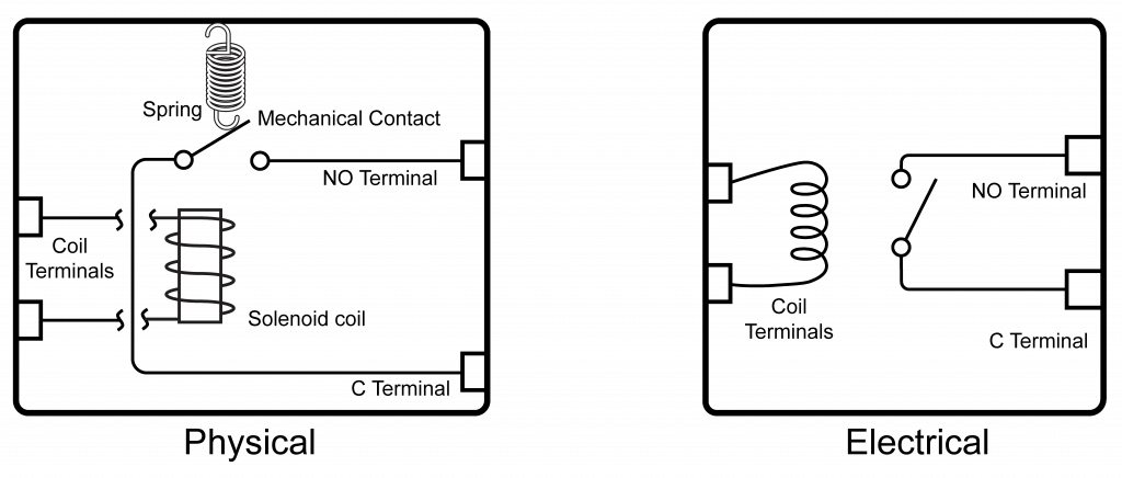
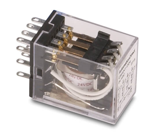
Common relays are electro-mechanical devices (Figure 2). They have an electric solenoid coil which is on the “control” side of the circuit. When this is energized, it moves the mechanical contacts on the “load” side from off to on.
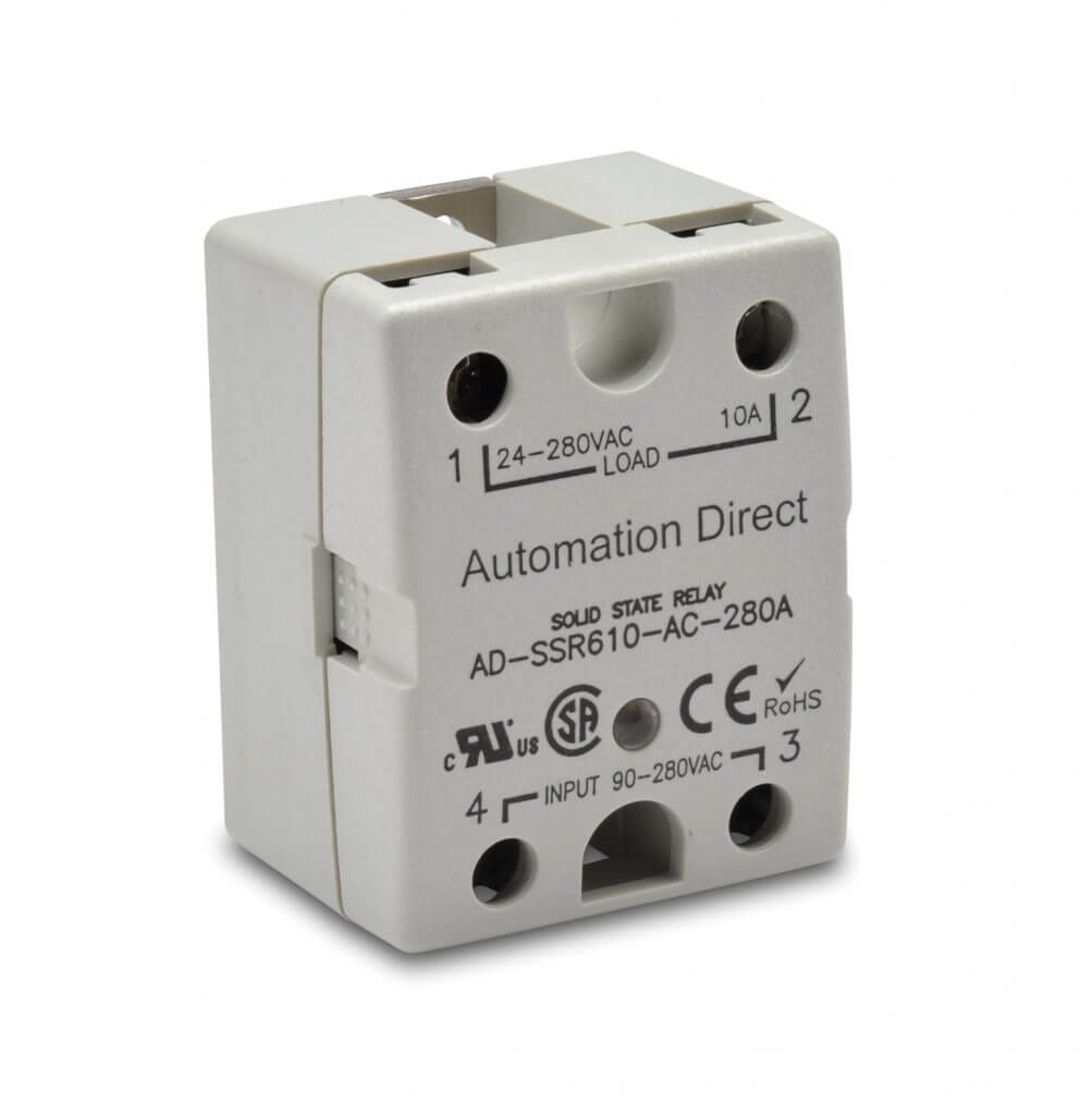
Another popular style is solid-state relays (Figure 3). These electronic devices use semiconductors to act as contacts. Since there are no physically moving parts, they can operate very quickly.
There are also other specialty types like latching, mercury-switched, reed, and thermal relays.
Electrical Ratings
Relay coils are rated to operate at a certain voltage and will draw a specified current when energized. The pickup voltage is the minimum voltage that will energize the relay, often about 80% of rated voltage. The dropout voltage is the voltage below which an energized relay will de-energize. An energized relay may be called pulled-in. Some relays may be rated with a higher inrush current to energize them, but a lower holding current once pulled-in.
Contacts are also rated for various voltages and currents, and this high-power side must be carefully matched to the load. When contacts are completely isolated from the coils, which is usually the case, they may be called dry contacts. Sometimes the external voltage connected to a dry contact is called a wetting voltage.
AC vs DC Relays
Coils can be AC or DC voltage and must be selected to match the available control circuit voltage. The AC versions are not polarity-sensitive, but the DC versions are, meaning positive and negative must be wired to the right connections. Some AC versions may experience hum or slight noise when energized.
Contacts are also rated for AC or DC voltage and must be selected to match the load. A special concern is that contacts must be able to quench the electrical arc that forms as the contacts are opened. Designers will find it much easier to select relays for switching AC loads than DC. This is because AC power cycles through zero volts and therefore the arc is more readily quenched. Since DC power is at a constant voltage, the arc is more likely to sustain.
Relay contacts have provisions for switching the rated current through millions of operations. Contacts for switching high current use special metals and designs to quench arcing. Contacts for switching very low voltages and currents may be gold-plated. A contact uses some kind of mechanical wiping action to clean itself and protect against corrosion and oxidation.
Relay Contacts
Relay contact connections are exposed on pins or terminals. These terminals may have other designations, but are usually called normally open (N.O.), normally closed (N.C.) and common (C). There are three main forms of relay contacts, which define how the continuity operates at the terminals:
- Form A, N.O., make contacts,
when energized, passes power between C and N.O. terminals - Form B, N.C., break contacts,
when energized, interrupts power between C and N.C. terminals - Form C, N.O./N.C., changeover or transfer
contacts (three terminals),
when energized, passes power between C and N.O. terminals and interrupts power between C and N.C. terminals
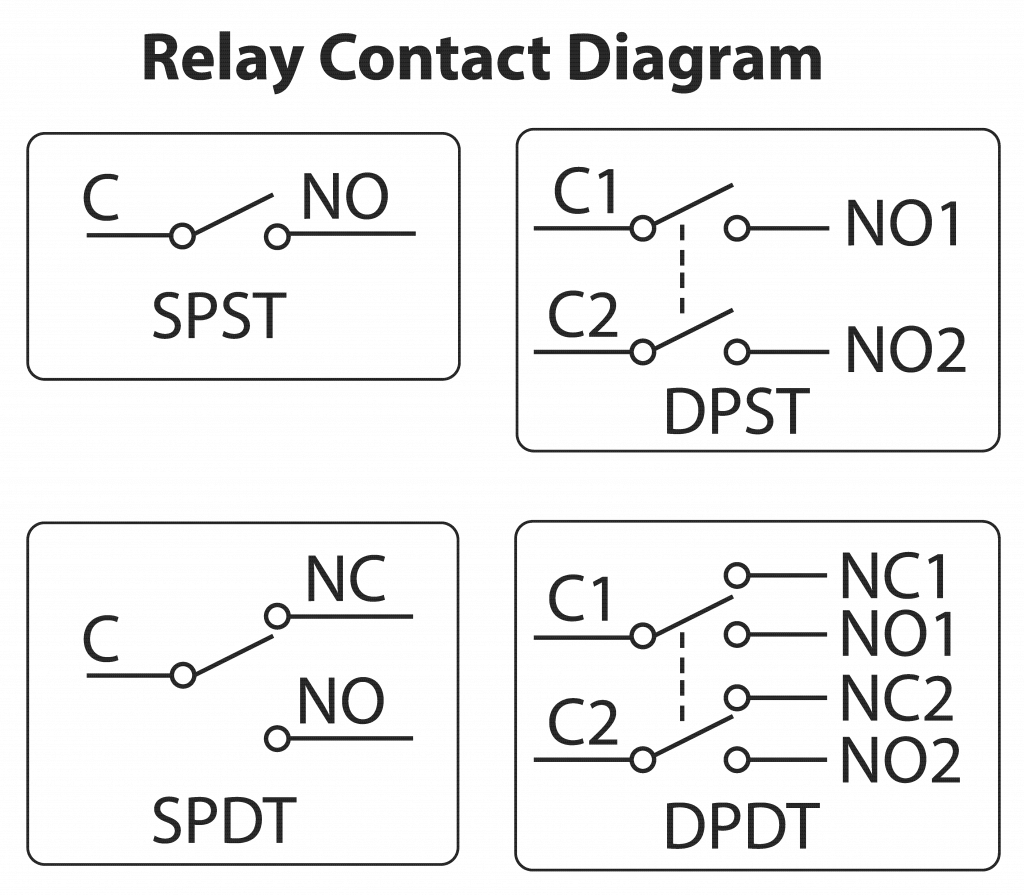
Relays can have many different contact arrangements and quantities (Figure 4). The term pole refers to how many isolated contacts a relay has, the most common being single-pole (SP) and double-pole (DP). The term throw indicates if a contact is Form A or B which would be single-throw (ST), or Form C which would be double-throw (DT). The most common configurations one would see on a specification sheet are:
- SPST
- SPDT
- DPST
- DPDT
- 3PDT
- 4PDT
When contacts are first energized closed, they sometimes bounce off and then back on briefly. This is imperceptible under most conditions, but on sensitive control and logic circuits this extra action can cause timing problems. Most contacts are simply on/off, but there are some special contacts called make-before-break and break-before-break that are mechanically arranged to perform those actions.
Special Relays
Basic relays are simply on/off devices, and they fail off to the off position when de-energize. However, a relay may be bistable or latching, which means it alternates when the coil is pulsed and then stays in that position until the next pulse shifts it the other way. These relays fail last in the last position. There are also relays with built-in functions like timer, on-delay, off-delay or pulsing functions. Sometimes these functions are mechanical, but more commonly they employ digital electronics. Some smart relays can perform functions similar to tiny programmable PLCs.
Relay Installation
Relays can have screw terminals, pigtail wires or be soldered into place. Older style relays and higher-current designs may be open with exposed energized parts. Newer and smaller designs are typically touch-safe, so users are less likely to come in contact with energized parts. For most industrial applications, a relay is used with a corresponding socket, which can be screwed into equipment or clipped on to a DIN rail. The socket is hardwired into place, and the relay can be easily removed and replaced. There are many socket sizes and formats, with two popular styles being blade and octal pin. Smaller control relays are often called ice-cube relays due to their size and shape resembling a cube of ice.
Relay Options
Depending on the need, relays are available with many options like:
- LED/neon indicator light
- Mechanical indicator flag
- Mechanical push-to-test button
- Diode or surge suppression protection
- Hold down clip for retaining relay in the socket
Design Considerations
Designers need to ensure the relay control circuits are compatible with selected relay coils, which usually means ensuring that a PLC DO has enough current to energize the relay. They also need to make sure that the contacts are suitable for all operating conditions. Relay coils consume power and generate heat in operation. Therefore, designers must calculate the heat load due to relays and allow for it.
Specifying surge suppression is key when interfacing a PLC to a relay. Without suppression, PLC discrete output points on the output card can be damaged by the spike created when the relay deenergizes.
By: Brent Purdy PE, Product Manager, Power & Circuit Protection at AutomationDirect