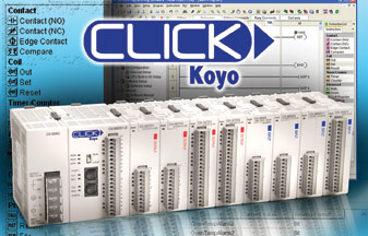
Will the CLICK PLC work with my C-more and C-more Micro graphics panels?
Yes. Currently the CLICK PLC driver is available in the C-more Micro panel with firmware version 0201001 or later, so native CLICK addresses are available.
The CLICK PLC driver for C-more touch panels is currently under development and scheduled to be available soon. You can communicate between the CLICK PLC and C-more touch panels with the standard MODBUS RTU protocol.
Where can I find the corresponding MODBUS address for the CLICK PLC registers?

The CLICK PLC Address Picker has an option to “Display MODBUS Address”. When this is selected you will see a column between the Data Type and Nickname with the title “MODBUS Address (Function code)”. This lists the actual MODBUS address for the corresponding CLICK address on that row. You also have a list of valid MODBUS function codes for that data type represented in parentheses, such as (03, 06, 16).
You also have two display options based on the type of MODBUS device you are using. You can display the MODBUS address as a 984 address or HEX address, for example:
DS27 400027 (984)
DS27 001A (HEX)
You have three options for entering instructions into the ladder logic.Do I have to use the mouse or can I use the keyboard when inserting an instruction into ladder logic?
With the mouse:
a. you can single click and drag from the instruction list into the ladder.
b. you can double click from the instruction list and populate at the current cursor position.
c. you can type the instruction abbreviation directly into the ladder at the cursor position.
There is an auto complete feature, so when there are no other possible combinations it will display the instruction dialog box.
Instruction keyboard shortcuts include:
NO (F2) Normally Open
Ctrl+F2 Immediate
NC (F3) Normally Closed
Ctrl+F3 Immediate
Shft+F2 Raising Edge
Shift+F3 Falling Edge
=, !, <, > Compare Contact
OUT Out coil
SET Set coil
RESET Reset coil
TMR Timer
CNT Counter
MATH Math
DRUM Drum
SR Shift Register
COPY Copy Data
SRCH Search
CALL Call Sub-routine
FOR For loop
NEXT Next instruction
END End instruction
RD Network Read
SD Network Send
You can also type certain data addresses directly. For a normally open contact, you can type any address for an input (X001), output (Y001), internal contact (C1), Timer (T1) or Counter (CT1). For a coil, you can type any address for an output (Y001).
How do I draw a branch circuit on a rung?
You can enable the line drawing tool from the Menu structure Edit > Line or click the icon. There is also an Edit > Erase Line tool or click .
You can also use keyboard shortcut keys for drawing lines in the ladder logic. To draw a line use Crtl+arrow keys so the line draws in the direction of the arrow key you press. Ctrl+Shift+arrow key will erase lines (rungs or branches)
Is there a power budget requirement with the CLICK PLC?
Yes and no, depending upon the power supply you are using to power your system.
If using the C0-01AC CLICK power supply there are no power budget concerns. The 1.3 amps supplied more than adequately handles any possible I/O module configuration. But, if you are using the C0-00AC CLICK power supply there are power budget considerations. The 0.5 amps supplied is not adequate to handle all possible I/O module configurations but may be suitable for many.
If you are using a different manufacturer’s supply or a system power supply, calculate your budget carefully. The System Configuration Setup window in the CLICK PLC software will calculate the power budget for you, either online or offline.
There is also a system configuration tool at www.clickplcs.com/config that will calculate the power budget, I/O count and price.
Can DirectSOFT or DNLoader be used with the CLICK PLCs?
No. CLICK uses its own programming software package and neither DirectSOFT nor DNLoader will work with CLICK.
Does CLICK support local expansion or remote I/O?
No. CLICK PLC is limited to 8 I/O modules for each CPU.
View products from AutomationDirect that relate to this article: CLICK PLCs
By Jeff Payne
AutomationDirect,
PLC Product Manager
Originally Published: Dec. 1, 2009

