Corona discharge happens when a conductor is forced to carry more electrons than it can accommodate. In these instances, the electrons jump to the air where they flow to any neutralizing charge that they may find. Near the conductor, the electrons have sufficient energies to ionize the air and force it to glow or, in other words, produce a corona.
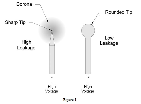
 The most common cause of electron concentration is sharp points on the conductor. The electrons concentrate at the diminishing point and eventually are forced off the conductor. As an example, the sharp tip of the conductor on the left hand side of figure 1 will have a great deal of leakage at high voltage and will, most likely, glow with a low purple light. On the other hand, the conductor on the right, with its rounded tip, will have very little leakage and will stand off much higher voltages.
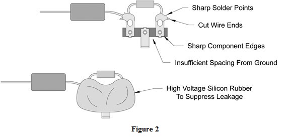
Solder joints are always a trouble spot in high voltage circuits. In one instance I designed and constructed a 10,000 volt DC power supply for an industrial flash unit. When I energized the circuit, it was outputting only 2000 volts. As I probed the circuit, it was clear that the voltage got progressively lower as I worked through from the transformer secondary to the output of the supply. This was puzzling. Without any other ideas, I turned off the lights and was surprised to see that the entire circuit was glowing brightly from numerous corona discharge sites. I turned on the lights, de-energized the circuit and carefully applied high voltage silicone rubber to all of the soldered and bolted joints. The next morning I re-energized the circuit and it produced its full 10,000 volt output. As it turned out, the solder and bolted joints were leaking 80% of the power supply’s voltage to air! Figure 2 shows an example of a poor high voltage solder joint and the use of high voltage silicon rubber to suppress leakage.
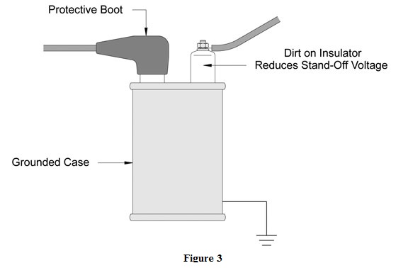
The slow build-up of dirt can also produce high voltage leaks. This is particularly problematic with equipment that is forced to operate in dirty and dusty environments. High performance cabinet filtration will help mitigate the effects of dirt built-up. Figure 3 shows how an exposed stand off insulator can be protected from dirt build-up by using a protective boot. In this case, the leakage would be from the terminals to the grounded case. If the case is floating, the leakage would be between the terminals, forming a bypass of the component.
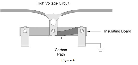
Carbon paths, as shown in figure 4, are insidious problems that build over time. There are two principal ways that carbon paths develop. The first occurs during uncontrolled arcing. The arc produces a great deal of heat and burns the surface of the insulator, forming carbon. If the arc has enough energy and the insulator is sufficiently burned, a permanent short can be produced. Glass or ceramic insulators with a glazed surface resist this type of damage, while phonolic and plastic insulators are particularly susceptible.
The second process that forms carbon paths is the slow carbonizing of dirt deposits. As dirt builds on the insulator, small micro-arcs accrue and produce localized carbon sites. As time progresses, the carbon builds until its leak rate is detrimental to the circuit’s continued operation.
In addition to the above methods, heat shrink tubing, especially the marine grade variety, will significantly help in reducing corona discharge and the formation of carbon paths. Even though it is usually considered unprofessional, in a pinch, even ordinary electrical tape does a pretty good job dealing with these troublesome situations. I also stress circuit cleanliness. Preventing dust and dirt buildup will dramatically reduce the formation of carbon paths. All it takes is a quick blast of dry compressed air and/or regular replacement of the cabinet filters.
I have found that heat shrink and boots will dramatically reduce corona discharge and carbon path formation; however, potting the joint in silicon glue stops discharge and the formation of paths altogether. In my experience, it can be pretty tough, or even impossible, to get into a finished circuit to apply heat shrink, boots or tape. For that reason, and because of the convenience of the long nose tip supplied with a tube of silicon rubber, I usually lean towards the glue solution. I will readily admit that caulking the joints of an electronic assembly doesn’t look that great, but it provides exceptionally good performance in this regard.
Brian Elliott Bio
Brian Elliott is currently V.P. of Engineering and Manufacturing at Air Options, Inc. During the course of his long career, he has worked in various industrial, technical and scientific fields ranging from automated manufacturing to high energy physics. He has authored two books, “The Compressed Air Operations Manual” (ISBN 0-07-147526-5) and “Electromechanical Devices and Components” (ISBN-10 0-07-147752-7), both are published by the McGraw-Hill Book Company. Both books are available through book retailers worldwide.
By Brian S. Elliott
Originally Published: Sept. 1, 2008


