Those of us who have worked with, or around, electrical equipment have witnessed electrical arcs. At the very least, we’ve seen the sparks produced when a relay or contactor switches off. Similarly, most of us also know that repetitive arcing can be very damaging to contacts over the long term, requiring periodic replacement of relays or their contacts.
Why Arcing Occurs
The principal reason for arcing is the inductive kickback produced by a coil when it is de-energized. When power is disconnected, a coil naturally tries to preserve the current. It does this by increasing the voltage. In some cases, this increase reaches several thousand volts, which easily promotes arcing across contacts and through the coil itself.
During this discharge, localized temperatures often become high enough to promote rapid erosion of the control contacts. Induction motors and solenoid coils represent the most common source of arc energy. This phenomenon is easily observed by watching a motor starter with open contacts. When the motor turns on, the contacts close in a fairly uneventful fashion. However, when the contacts open, there is a bright, momentary arc produced which is visible to the naked eye. This arc represents the inductive energy stored in the motor coil.
Another common source of arcs occurs when energized components are placed too closely to an opposite potential. When properly utilizing commercially available components, a proximity situation rarely occurs. There are, however, several situations which promote arcing. Obviously, using components at higher voltages than they are rated for reduces their effective stand-off voltage, thereby creating an arc. Electrical components should never be used at voltages higher than the manufacturer’s recommendations. Over the long term, dirt also becomes a factor. As dirt builds up on electrical components, standoff voltages may decrease until an arc initiates. One of two things happens at this point; either the arc energy blows away the dirt build-up and the component returns to normal operation, or the dirt burns and a carbon path is produced on the insulating surfaces of the component(s), permanently reducing the stand-off voltage. This, in turn, promotes more arcing, which causes more damage and a run-away situation can rapidly form. If the power source is sufficient to maintain a continuous arc, then extreme damage to the contacts and surrounding components can occur in very short order.
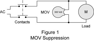 Controlling arc damage from coils and motors is done by suppressing inductive kickback. There are three basic methods which can mitigate inductive kickback: shorting, arc lengthening and switching management. For lower power applications, such as small solenoids and fractional horsepower motors, shorting is the simplest method. Shorting can be accomplished by using a metal oxide varistor (MOV), a neon lamp or a spark gap. An MOV is the most common component used to suppress lesser energies. These devices represent an open circuit below their specified rating and become conductive above that rating. An MOV is connected directly to the terminals of the coil. When the coil is disconnected, its voltage starts to rise, and when it reaches the MOV rating, its output becomes shorted. All arcing is suppressed because the kickback voltage is never large enough to initiate the arc in the first place. Figure 1 shows how an MOV is used in a circuit to suppress inductive kickback.
A neon lamp serves the same basic function as an MOV, with slightly less precision and at lower voltages. In this case, when the voltage climbs high enough to light the lamp, the inductive energy dissipates through the element. When neon lamps are used for transient suppression, they are placed in the same location as the MOV in figure 1.
 A spark gap can also serve to suppress inductive energies. Once again, the protective element is placed across the terminals of the coil. As the voltage rises, it eventually reaches a point which causes a spark to form across the gap; the idea being that the arc gap will initiate a spark before the control contacts.
MOVs, neon lamps and arc gaps have practical limitations. For applications involving higher energies, such as multi-horsepower motors or an entire branch circuit, controlling inductive kickback through shorting simply isn’t practical. Usually, arc lengthening is used for these applications. In these cases, the arc is lengthened until inductive energies can no longer sustain the reaction.
Four Methods to Lengthen an Arc
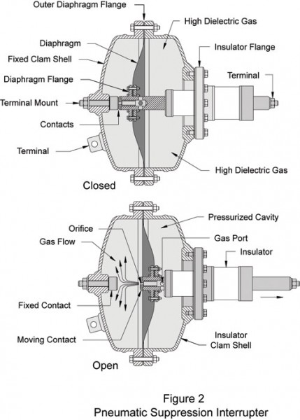
There are principally four methods used to lengthen an arc: long-throw contactors, pneumatic suppression, magnetic suppression and arc dividing. Long-throw contactors have the disadvantage of being disproportionately large in comparison to other techniques; therefore, these devices are not commonly used. Pneumatic suppression is typically used for switching situations which deal with extremely large inductive energies. Pneumatic suppression interrupters, as illustrated in figure 2, are most commonly used to switch large elements of the power distribution grid throughout the United States.
Magnetic Suppression
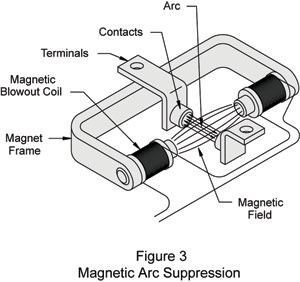
Magnetic suppression and arc dividers are typically utilized when switching multi-horsepower motors. Magnetic suppression is accomplished by forcing the arc to follow the longer field lines of a fixed magnet placed in close proximity to the contacts. The longer path is specifically designed to force an arc length that can’t be sustained by the availableinductive energies. Figure 3 shows a schematic representation of magnetic arc suppression.
Arc Dividers
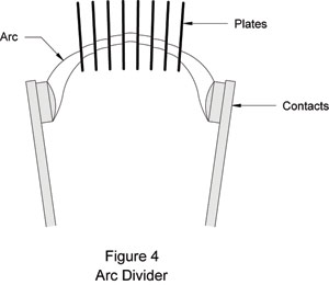
Arc dividers are typically a set of high-temperature, insulating plates arranged just above the arc formation area. The idea is that the heat generated by the arc forces it to rise into the plate array. This has the effect of dividing the arc into several sections, which immediately extinguishes it. Arc dividers are generally used for higher horsepower applications and long throw interrupters. Figure 4 shows a schematic representation of an arc divider.
Switch Management
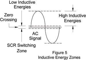
Switch management represents the cutting edge of arc suppression technologies. In these cases, a high speed, solid-state switch element is utilized. Usually a silicon-controlled rectifier (SCR) or high-power transistor set makes up the switch element. If the switch can be turned off at or near the zero crossing of the AC signal, then the coil will have substantially reduced inductive energies and the damaging effects can be principally negated. SCRs are rather popular for these applications because they operate with AC power and turn off when the line current drops below a given level very near the zero crossing. This characteristic of SCRs makes them nearly ideal for switching AC devices with a high inductive component. Figure 5 shows an AC cycle and its associated inductive energy zones.
Since arcs have a tendency to jump toward a neutralizing potential, this makes them a severe safety hazard. It is very important to de-energize and discharge any electrical equipment that is being serviced. This is particularly important with circuits having storage potential, such as high-voltage capacitors. Devices like this retain a lethal electrical charge well after the power has been disconnected. Many circuits have what is termed a “crowbar”, which is a relay which shorts and discharges any components with storage potential when the power to the equipment is disconnected.
Safety procedures and devices implemented and used on and around high voltage circuits are, to say the least, extremely important. When working with this type of equipment, these procedures and devices mean the difference between a safe working environment and serious injury, or even death. In part two of this article, we’ll discuss safety procedures and equipment commonly applied when working with or designing high voltage electrical equipment.(Sources, Suppression & Safety Considerations) Read Part Two of the series here: http://library.automationdirect.com/electrical-arcs-part-2-of-a-2-part-series-issue-19-2011/
By Brian S. Elliott[hozbreak]
Originally Posted: Sept 1, 2010


1 Comment