Indirect addressing, or pointer addressing as it is called with Koyo PLCs, is an addressing mode found in many processors’ instruction sets that specifies a register that contains the effective address. Accessing the operand requires two memory accesses – one to fetch the effective address and another to read or write the actual operand. Indirect addressing has many uses, the most common of which is lookup tables. You could perform numerous compare statements for the same function, but lookup tables can cut your programming time and number of rungs considerably.
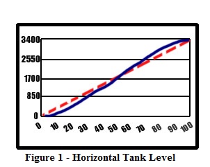
For instance, finding the number of gallons in a horizontal tank is a fairly long and complex math process that can take up a lot of scan time. It certainly isn’t a linear equation as seen in Figure 1. The dashed red line indicates a linear line and the blue line shows the actual gallons in the tank. The equation for this curve is:
g = (L*((r^2*(ACOS((r-h)/r)))-(SQRT(2*(r*h)-h^2)(r-h))))/231
Where g=gallons, L=tank length in inches, r=tank radius in inches, and h=liquid height in inches. It’s pretty easy to see that this would be difficult to implement in ladder logic.
So how do we accomplish this without performing the entire difficult math equation? The answer is to pre-calculate several “points” across the scale and then do a linear calibration equation between those points.
Obviously, this method will induce a certain amount of error since you are taking a curve and slicing it into divisions and then performing a linear calculation on the individual divisions. The more divisions, the less error, but the more CPU memory consumed.
Creating the lookup table can be performed in several different ways. One way would be to take the manufacturer’s table and cut it into equal divisions. Next, find the values at these divisions and place the engineering units at those divisions into the table. Then, divide the raw units by the same number of divisions and use this to perform the lookup.
Another method is by calculation estimation. For example, you might take the equation and place it into a spreadsheet and derive the engineering units by calculation. Still another option is by manual calibration, although this method is sometimes nearly impossible to accomplish.
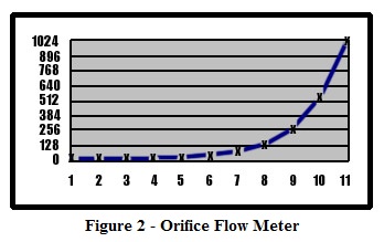
In the following example, we will be using the manufacturer’s table method, with a non-linear analog value, such as an orifice flow meter. In order to scale the non-linear signal, we need to divide the raw analog signal into sections. If we divide the raw analog value (4095) by 10, we have 11 sections, 10 of 409 units and 1 remainder of 5. We also need to divide the manufacturer’s table into engineering units by dividing into 11 sections. For this example, our engineering units will be 0, 1, 2, 4, 8, 16, 32, 64, 128, 256, 512, and 1024 (See Figure 2). This is where the numbers for the lookup table come from.
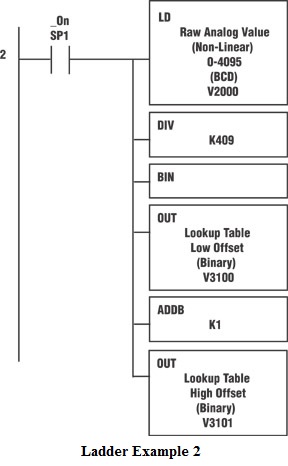
In our ladder program, the first step is to load the lookup table values into V-memory (variable memory). Anytime you have variables that will not change often (if ever), load them during the first scan cycle as shown in Ladder Example 1. This will save frustration if something should ever happen to the V-memory, such as forgetting to install a battery for backup.
Ladder Example 1
Load the non-linear table on the first scan
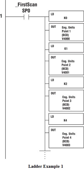
To find the lookup table offsets (which are the high and low values that fall below and above the actual measured raw values), we take the raw analog input signal and divide it by the unit number 409. This gives us the lookup table low offset value. We will add one to this number to obtain the high offset value. These values will be used to index the lookup table. (See Ladder example 2.)
Ladder Example 2
Divide the raw analog value by the 409 (max analog counts divided by 10). The result will be the low and high offset.
All pointer addressing in DirectLogic PLCs is done as a hexadecimal equivalent of an octal V-memory address. In other words, take the octal address (for example V2000), drop the ‘V’ from the front of it and change to octal (O2000), and convert to hexadecimal (octal 2000 = hex 400.) If just thinking about this makes you dizzy, you can use the Windows calculator in scientific mode to perform the conversion. Also, there is a document on the Technical Support section of the AutomationDirect.com Web site that can help you with the data types as well. It can be found at:https://support.automationdirect.com/docs/an-misc-013.pdf.
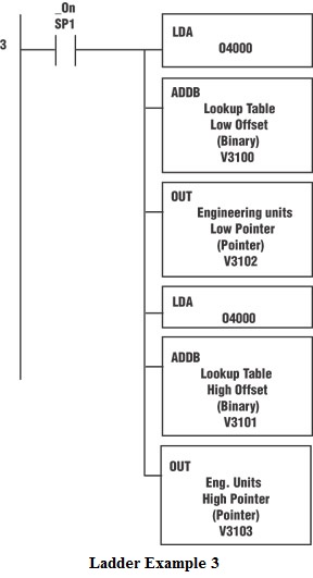
We will take the starting V-memory address of our table (V4000) and convert it to hexadecimal (800). Next, add the offsets, which were created above, to get the actual address pointers that we will use later. (See Ladder Example 3.)
Ladder Example 3
Add the index created in Ladder Example 2 to the lookup table start address (V4000) to find the actual address of the engineering unit values, high and low.
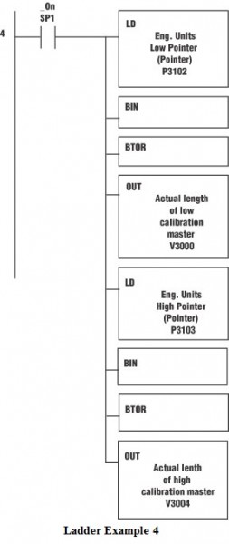
Now that we have the addresses of the engineering units that we need, we will load those values into memory locations for calibration. In Ladder Example 4, the LD “P3102” will peek into V-Memory location V3102 and see what address is stored there as a hexadecimal number. It will internally convert that to an octal number and use it as the address to get the accumulator data. For example, if V3102 is equal to hexadecimal 802, it will convert this to octal 4002, then it will look into V4002 to find the number (V4002=2) that will be placed into the accumulator.
Ladder Example 4
Convert the low and high scale values to a “real number” format
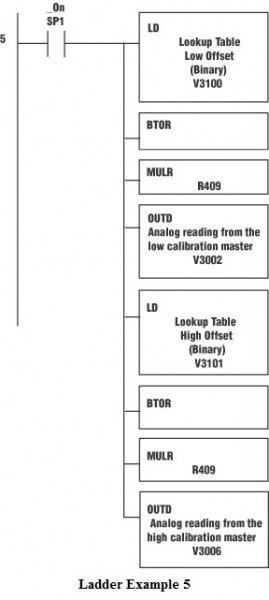
Now we need to know the “low” and “high” raw unit values for the range we are calibrating. Ladder Example 5 shows how to calculate the raw unit values based on the table offsets that were calculated in Ladder Example 2.
Ladder Example 5
Convert the calculated low and high scale values for the raw units into a “real number” format
We are now ready to perform the analog calibration. This is covered in the FYI article on pages 28 and 29, Implementing a PLC Calibration Routine to Ensure Accurate Instrument Readings.
For other example ladder logic programs, please visit www.automationdirect.com’s tech support home page and click on example programs. Follow the instructions on the page to view zipped files. (Note: DirectSoft software is required to view the sample programs. If you do not currently have DirectSoft, you can download a free demo version athttps://support.automationdirect.com/demos.html)
By Richard Palmer
AutomationDirect
Originally Published: Sept. 1, 2004


