In manufacturing facilities, compressed air is so widely used that it is often regarded as the fourth utility after electricity, natural gas and water. But compared to electricity, compressed air is more expensive, so why is it so widely used to drive factory automation systems?
The main reasons are lower upfront and maintenance costs, which combine to make pneumatics the most popular and cost-effective choice for executing mechanical motion. While there are some, especially electric actuator vendors, who claim electric motion is better due to its superior energy efficiency, it’s hard to beat the simplicity and reliability of pneumatics.
Linear Power Transmission Options
Linear power transmission is typically done with fluid (pneumatic with air or hydraulic with oil) or electric power. In electric power systems, electromechanical devices such as belts, pulleys, chains, sprockets and clutches convert rotational motion from motors to linear force. The main exception is linear motors, a relatively expensive specialty technology used to move very light loads.
Although many vendors often promote the competing technology of their choice, the choice of power transmission depends on the application. It’s not uncommon for larger machines to have all three of the power transmission technologies in use simultaneously. But many other machines only use pneumatics due to some advantages over other power methods.
Linear Power Transmission Comparison
The table below lists some of the general advantages associated with pneumatic, hydraulic and electrical means of producing linear mechanical motion.
| Characteristics | Pneumatic | Hydraulic | Electric |
| Complexity | Simple | Medium | Medium/High |
| Peak Power | High | Very High | High |
| Size | Low size/force | Very Low size/force | Medium size/force |
| Control | Simple valves | Simple valves | Electronic Controller |
| Position Accuracy | Good | Good | Better |
| Speed | Fast | Slow | Fast |
| Purchase Cost | Low | High | High |
| Operating Cost | Medium | High | Low |
| Maintenance Cost | Low | High | Low |
| Utilities | Compressor/power/pipes | Pump/power/pipes | Power only |
| Efficiency | Low | Low | High |
| Reliability | Excellent | Good | Good |
| Maintenance | Low | Medium | Medium |
Pneumatic systems are simpler than hydraulic and electric systems, conferring advantages in upfront costs and maintenance. Fluid power systems produce linear motion with simple pneumatic and hydraulic cylinders and actuators. Converting electrical to linear power often requires one or more mechanical devices to convert the motor rotation.
Pneumatic and hydraulic power transmission methods typically produce more power in a smaller space, so small pneumatic cylinders can be used to provide the high required clamping or positioning force needed to hold a product in certain machining and other applications.
Control of this power is usually easier with pneumatics and hydraulics than with electric systems. A simple valve, regulator and flow controls are usually all that’s needed to control cylinder direction, speed and force. An electric actuator often needs an electronic controller, multiple I/O points, communication cables, and possibly encoder feedback, along with more complex automation system programming.
A pneumatic actuator typically has two very repeatable end-of-travel positions which are set by using a hard stop, cushion or shock. Electric actuators are also very repeatable, and can be easily designed with multiple stop positions. With new advances in electronics, pneumatic control of multiple stop positions is also now possible. Whether it is end-of-stroke or multiple stop positions, both pneumatic and electrical actuators can attain the desired position at high speeds.
“Pneumatic hardware is also much simpler to design, and less expensive to purchase and install.”
Operation of a compressor may have additional costs compared to electric, but the availability of clean dry air in a facility is common. And pneumatic components often have the lowest maintenance costs, such as when replacing seals, or a whole cylinder for that matter, which is often much cheaper than servicing, let alone replacing, an electric actuator.
Noise is becoming less of a concern with fluid power devices. Designs have improved over the years, greatly reducing clatter to about the same level as a stepper-driven electric actuator. New improvements in designs and efficiency of compressors, and the standard use and distribution of clean dry air in a manufacturing facility, also make pneumatics a good choice for industrial automated machinery.
A Good Application for Pneumatics
Pneumatic power transmission methods are often the best way to move parts and tooling in industrial machines. These pneumatic systems perform a myriad of tasks in automated equipment such as clamping, gripping, positioning, lifting, pressing, shifting, sorting and stacking. Some adaptive uses—each of which could include closed loop control for more precise positioning—include tensioning, pressing, labeling, embossing, crimping and cutting.

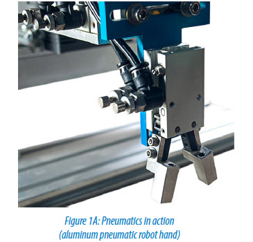
The tried and true pick-and-place method with horizontal and vertical travel and a gripper is probably one of the most common uses of pneumatics. Clamping or part positioning functions are also widely implemented with pneumatics. If tooling needs to move, a part needs to be held, or a force or tension needs to be applied, pneumatic systems can likely provide a solution.
Basic Pneumatic Hardware
All pneumatic systems will have certain basic components. The first is a compressor, and then a system to distribute the clean, dry air it produces.

Common pneumatic components on automated machines include:
- air preparation system (shut-off/lock-out, combination filter/regulator, soft start valve)
- control valves and manifolds (manual, air pilot, solenoid operated)
- air cylinders and actuators
- tubing and hoses
- push-to-connect fittings
- cylinder position sensors
- discrete pressure switches
- specialty components and accessories
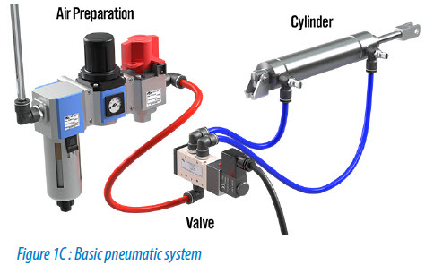
Since most facilities have a plant air supply, the machine pneumatic system starts with the air preparation unit to which the plant air is connected. The air prep system should include a manual and lockable shutoff valve, filter, water trap and pressure regulator. It should also have an electrically-operated soft start to remove air during an emergency stop, guard open or similar safety event. The air prep system may also include a lubricator, but it’s usually not necessary unless pneumatic rotary tools are in use.
The air prep system typically feeds the valves or valve manifold that can include manual, air-piloted and solenoid-operated control valves to turn the air supply off and on. These valves feed control air to a variety of pneumatic cylinders and actuators where power transmission happens.
Pneumatic cylinder position sensors and pressure switches are a common component in pneumatic systems. There are also a wide variety of special pneumatic components such as flow controls, quick exhaust valves, hand valves, check valves, inline pressure regulators, gauges and indicators.
Getting Started
With pneumatic systems, a little guessing is okay, but be sure to understand the application. How much force do you need? How fast do you need to move?
With pneumatic power transmission, it is important to define the mass of what is going to be moved along with its velocity and acceleration profile. The required power to be transmitted to the part or tooling must also be specified. With that information and mounting decisions made, the cylinders, tubing and valves can be specified.
Pneumatics is the best choice in many applications, unless you need the highly accurate and programmable motion positioning offered by electric systems, or the very high levels of force provided by hydraulics. But in most cases, pneumatics can provide a simple, reliable, cost-effective solution. So, in your next motion application ask yourself, “Why not pneumatics?”
Check out AutomationDirect’s pneumatics offerings here.
By Pat Phillips, Fluid Power and Mechanical Products Product Manager, AutomationDirect
Originally Posted: Jan. 28, 2016


