In order to perform a task using pneumatics, there needs to be some way to initiate, monitor, and stop the process. This is where a simple pneumatic system becomes electro-pneumatic. Electro-pneumatic systems integrate pneumatic and electrical technologies into one system where the signal/control medium is electrical and the working medium is compressed air. In this type of system, devices like relays, solenoid valves, limit switches, and PLCs can be used to interface electrical control with pneumatic action. There are basically two areas to focus on with the electrical side of an electro-pneumatic system: how to start/stop the process and how to know what the system is doing.
Who’s the Boss?
In many electro-pneumatic systems, the device being controlled is an electrically actuated directional control valve. These control valves supply air pressure to devices like cylinders that will extend or retract a rod when pressure is applied or removed. Built-in solenoids are used to open and close these valves and are activated with AC or DC voltage signals. Looking at the conveyor configuration below, notice the diverting conveyor between the two conveyor lines. This diverter is used to return boxes that aren’t filled properly and it is pneumatically raised and lowered when the selected boxes are in position. In this example, there are a few different ways to control the solenoid air valve responsible for raising and lowering the diverter.
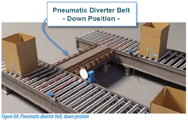
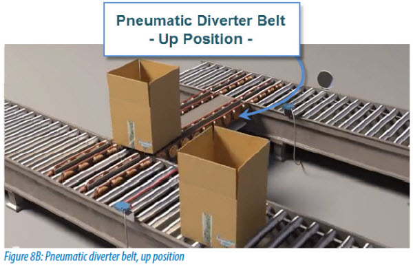
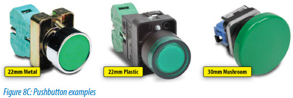
The first option is manual control, using a device like a pushbutton. With a single momentary pushbutton and a voltage source, the operator can determine when the belt will raise or lower by pressing the pushbutton and closing the normally open contacts within. Once closed, the supplied voltage will be provided to the solenoid and the control valve will open allowing air flow to the cylinders. The cylinders will extend and the belt will raise into the diverting position. When the pushbutton is released, the air flow will stop, the cylinders will retract, and the belt will lower to its initial position. Although the simplest way to provide electrical control, the manual method requires the operation to be manned at all times.
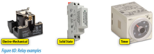
Another option for electrical control is the use of relays. When a relay’s coil is energized by an electrical signal it will close or open the normally-open or normally-closed contacts within. By connecting the pneumatic control valve to a relay contact and an object detection device, like a photo eye, to the relay’s coil, the system will activate the pneumatic action automatically. Once a box is in position and detected by the photo eye, the relay’s coil will energize and in return a voltage signal will be sent to the control valve. Once again the cylinders will extend and the belt will raise. Relays are available in both electromechanical and solid state versions and in this scenario, a time delay relay or latching circuit may also be needed to ensure the box has traveled the length of the belt before the belt is retracted.
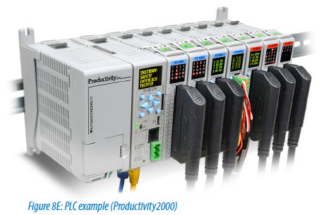
In a more complex system with numerous valves, relays may become too cumbersome to install, modify and maintain. This is where PLCs reign supreme. PLCs can not only handle many logical inputs and control outputs, but they can also easily integrate timing functions, sequential operations, alarming, remote visibility, etc. into a pneumatic application. With a PLC, the photo eye is wired to an input module and the control valve is connected to an output module. Logic code within the PLC will determine when to activate the control valve output using the transitions in the photo eye input. Additional code can also be written for latching functions, alarming, data logging, etc. For more information on PLCs and PLC programming, see The PLC Handbook – A Practical Guide to Programmable Logic Controllers eBook here.
That Makes Sense!
Another important component of electro-pneumatic systems is feedback. Feedback devices inform the operator of system status and whether or not the requested task has been completed, or even attempted. Three important things to know when it comes to pneumatic systems are pressure, flow and position.
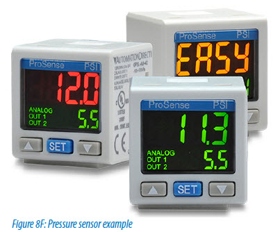
Pressure in pneumatics is similar to voltage in electricity. They both represent the potential energy available in the system. The difference in pressure from one point to another is what causes air flow in pneumatics the same way the voltage difference between two points causes current flow in electricity. So, the amount of pressure available is an extremely important component. To measure this pressure, pressure transmitters or pressure switches can be installed in the pneumatic circuit. Some applications, like pneumatic stamps, may also use pressure sensors to detect the optimal pressure applied during the stamping operation.
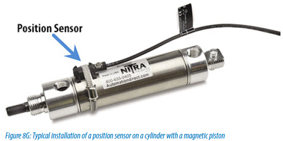
Flow is also important as it represents the speed at which cylinders extend and retract. In other words, at a given pressure, flow rate determines the rate of energy transfer (i.e., horsepower) the system will supply. This can be monitored using flow sensors and controlled using flow control valves. Flow switches will inform you if the air flow reaches a set value and flow transmitters will tell you the exact flow value detected. Position tracking in electro-pneumatic systems, like our conveyor, is accomplished by tracking the position of cylinder pistons or the devices they are connected to. Many cylinders have magnets built in to the piston that allow magnetic switches to detect the position of the cylinder. These switches can be mounted directly to the cylinder housing, as seen below, and detect when the piston is fully extended or retracted.
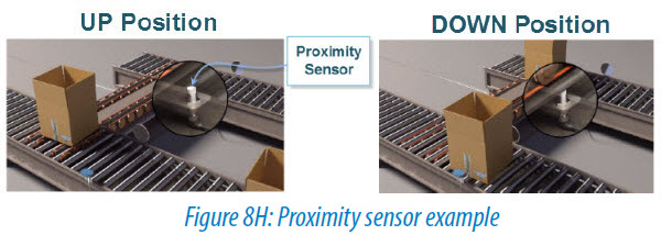
Another option with position detection is to use proximity or limit switches external to the cylinder. Proximity switches will detect position using magnetic, ultrasonic, inductive or capacitive means and limit switches will determine position by physically contacting the device being moved. Various types of limit switches are available, including ones with plungers, levers, rollers, and rods. Looking at the conveyor example, the position of the diverter belt is determined by using a proximity switch mounted underneath the conveyor. When the belt is lowered it moves into the range of the proximity switch. The switch then sends a signal to the controller indicating that the diverter is in its lowered position.
A limit switch with a plunger could have also been used to determine the conveyor position but limit switches have mechanical components that can wear out over time and in applications with frequent movement, a solid state device is preferred. If you would like more information on object detection devices and how to use them, please visit our Object Detection video cookbook series.
Additional Options
There are many other devices available that can make your pneumatic system safer and more intelligent. One example of a safety device in pneumatics is the soft start valve. This valve is used inline with air preparation components and it will slowly ramp up the system pressure to the desired level when its solenoid is energized. This way when a pneumatic system is coming online, the initial pressure will slowly increase in the system ensuring cylinders and other components do not slam into position. The slamming can damage components or injure any personnel unaware that the system is going live. Once the system pressure has reached the set point, these valves become transparent to the system. Also, soft start valves can depressurize the downstream pressure when the solenoid is de-energized. This can be tied to an Estop circuit to automatically dump the downstream pressure when an emergency is present.
Adding an electro-pneumatic transducer to a pneumatic system will also provide more control of system pressure. These devices, often called I/P converters, will take a current signal and convert it to a proportional pneumatic pressure value. I/P converters are used to achieve accurate, repeatable pressure when precision control of pneumatic actuators/operators, pneumatic valves, dampers, vanes, etc. is required.
A recent advancement in electro-pneumatics is the fieldbus-networked valve manifold. This new technology allows pneumatic manifolds to be monitored and controlled over industrial Ethernet networks. When used with PLCs, it allows the controller to more efficiently turn valves on and off without the usual hardwiring, and to gather I/O data from sensors, relays, individual valves, or other I/O devices via communication networks. With Ethernet technology, these manifolds can also integrate an on-board web server, which can make the manifold accessible to any standard web browser. Email capability is also possible and allows the manifold to send email messages containing information like diagnostic data when triggered.
Check out more articles related to pneumatics here or download our eBook below!