The 4-20mA analog current loop is a workhorse of automation, but initial setup and troubleshooting can be challenging, here are some tips to help.
For all types of industrial machinery and automation, a basic 4 to 20 milliamp (4-20mA) wiring scheme has been one of the most prominent installation methods for transmitting analog signals. Digital fieldbuses, and IO-Link in particular, are changing this a bit by providing a more advanced type of connectivity, but a 4-20mA analog current loop is the tried-and-true method of transmitting field measurements such as flow, level, pressure, temperature, and much more among devices and to a digital control system input point.
Although most loops are easy to install and commission, sometimes there can be a snag on initial setup, which requires a bit of troubleshooting to overcome. This article looks at some 4-20mA basics, and how to check on problematic installations.
4-20mA Basics
A basic 4-20mA connection conveys one analog value, and it also supplies operating power to 2-wire field devices. Devices classified as 4-wire require a separate power source and aren’t covered here. Some key benefits of 4-20mA loop powered installations are:
- The minimum value of 4mA is called a “live zero”, and it provides a baseline amount of power to the field device, while also making it easy to detect an open-loop failure (where a wire is disconnected or broken, causing the loop to go to 0mA).
- Cables can run long distances, up to thousands of feet.
- The signal is relatively immune to electrical noise, especially when shielded cable is used.
- Inserting a 250Ω resistor in the loop produces a 1-5VDC signal, which is another popular, although lesser-used, standard.
- Design is straightforward.
Each 4-20mA loop must be powered, usually with 24VDC for industrial systems. There are two parts of the configuration to consider:
- Sourcing: This means that the field device, a PLC I/O point, or a separate power supply creates the power. Field devices that are source are sometimes called four-wire because they have a separate power connection of some type.
- Sinking configuration: This means that the field device (or PLC I/O point) requires externally generated power. This is a true two-wire connection.
One element of any loop performs the sourcing, while all other elements do the sinking. Although it is possible for either a PLC I/O module or a field device to source the loop power depending on make and model, this article will focus on the most basic “2-wire” configuration with a separate 24VDC power supply sourcing power for both a field device and a PLC input configured for sinking operation. Figure 1 shows this 2-wire configuration, and also the common “3-wire” and “4-wire” configurations.
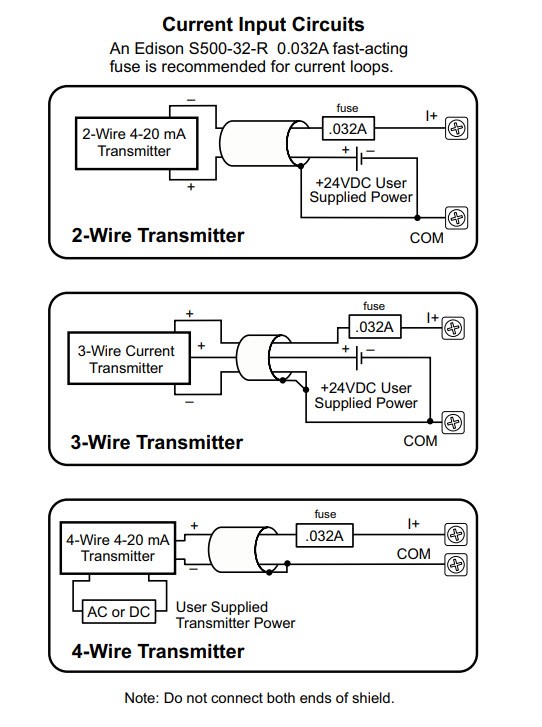
Figure 1: This diagram shows the most common 2-wire, 3-wire, and 4-wire analog 4-20mA control loop wiring configurations.
Field Transmitter/Instrument/Device
For our example, let us assume the field device is a Stego 014202 temperature/humidity device, which can actually has two on-board sensors that can transmit two separate 4-20mA signals. The device is wired with a standard M12 4-pin A-coded round plug connector for convenience (Figure 2).
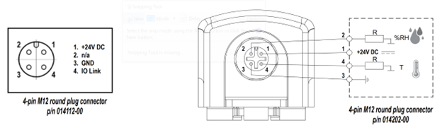
Figure 2: This Stego temperature/humidity transmitter is actually two 2-wire transmitters in one unit. Users can investigate one 4-20mA loop at a time following the steps in this article.
In this arrangement, the following connections must be made:
- +24VDC from the power supply must connect to “+24VDC” pin 1.
- 0VDC from the power supply must connect to ground “GND” pin 3.
- Note: It is possible to operate the power supply with the 0VDC connection “floating,” but best practice is to connect the 0VDC connection to control panel ground which provides a known “reference” for the signal.
- Considering just the temperature signal, the “T” pin 4 would be connected to a PLC input module. Note that the PLC input module would need the “common” connection wired to 0VDC/ground.
- Considering just the percent relative humidity signal, the “%RH” pin 2 would be connected to a PLC input module.
Once all of this is done, the PLC should be reading signals proportional to the measurements made by the field device. Scaling can be an issue because the PLC must convert the raw field signal into counts or engineering units. For this Stego device, the data sheet informs us that scaling would be:
- Temperature
- -40DegF = 0% = 4mA
- 140DegF = 100% = 20mA
- %RH
- 0% = 4mA
- 100% = 20mA
Troubleshooting Steps
But what if the system is connected this way, and it isn’t working as expected? Is the problem with the transmitter, or the PLC input/configuration, or the wiring in between? One approach is to use a clamp-on 4-20mA current meter to inspect the loop current without breaking a connection, or use a 4-20mA generator to simulate a signal, but not everyone has this style of meter handy. Here are two additional troubleshooting methods to investigate the issue.
Check the transmitter
One way the problem can be investigated is by isolating the sensor/transmitter from the PLC input, to see if the proper signal is being sent:
- Preserve the connection of the power supply +24VDC to sensor pin 1 and 0VDC to sensor pin 3.
- Remove the wire connected to sensor pin 4 for T (or pin 2 for %RH). It is typically easiest to do this at the control panel.
- Connect a 250Ω resistor from the transmitter side pin 4 wire (or pin 2 wire) to 0VDC or ground.
- The transmitter will be driving a loop current through the resistor.
Based on Ohm’s law, which is V=I*R, applied to just the resistor in this new loop configuration, we know resistance R, and we can measure voltage V with a multimeter, to determine the effective current I in amps. The basic expected values are:
- 0% = 4mA = 1VDC
- 25% = 8mA = 1.25VDC
- 50% = 12mA = 2.5VDC
- 75% = 16mA = 3.75VDC
- 100% = 20mA = 5VDC
By reading the voltage and applying some extrapolative math, it is possible to determine what signal the transmitter is sending. If the transmitter signal seems correct, it is time to look toward the PLC for further diagnosis. Of course, if the voltage is less than 1VDC or greater than 5VDC, then a problem with the device or wiring is indicated.
Note that this approach works for any resistance value if the math is adjusted. However, most loops require total loop resistance to be less than 500Ω, and a minimum of about 100Ω should be used to ensure a usable voltage reading.
Check the PLC input
On the other hand, if there is a concern that the transmitter is fine, but PLC input is not operating as needed, then another troubleshooting step can be performed by using a common AA battery to generate a nominal loop current.
- Preserve the connection of the power supply +24VDC to sensor pin 1 and 0VDC to sensor pin 3.
- Remove the wire connected to sensor pin 4 for T (or pin 2 for %RH). It is typically easiest to do this at the control panel.
- Connect a standard AA battery with the “+” going to the control panel side (not the transmitter side) in series with a 250Ω resistor, and the “-” going to 0VDC or ground.
- The battery will be driving a loop current through the PLC analog input.
Again, based on Ohm’s law, we would expect this to result in a loop current into the PLC analog input of 1.5V/250Ω = 6mA, which in turn should correspond to 12.5% of scale within the PLC. If a different resistor size is used, alter the math accordingly. Once this circuit is made, and if the PLC is not reporting the expected value, it is time to investigate the PLC wiring and configuration further.
4-20mA loops are Workhorses
Using 4-20mA current loops to transmit analog signals is a straightforward and reliable approach. Once commissioned, users can expect decades of dependable performance. However, once in a while there can be a hiccup during installation or operation. Following these basic steps will help isolate the source of any issue and put your team on the road to success.