The Conclusion of a Two-Part series
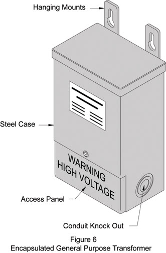
In the last issue of NOTEBOOK, we discussed the two categories of transformers commonly available and typical applications for them. The final category is control transformers, which are commonly incorporated into a machine element. This is the broadest category, as voltage matching situations will almost certainly be encountered which, in most cases, can be easily addressed with a transformer. In this category, high efficiency transformers are quite desirable because they are considerably smaller and produce less heat than their standard counterparts. Figure 6 shows a typical encapsulated transformer that is appropriate for general purpose applications.
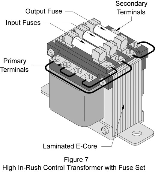
In most machine and automation applications, control circuits operate at either 24 or 120 VAC. These lower voltages produce significantly safer circuits, which can be completely isolated from the higher line voltages used to power the equipment. Control transformers are typically configured specifically for these applications. Figure 7 shows a typical high inrush “E” core control transformer that is configured with a three-element fuse block. One fuse is used to protect the output and two are used to protect the input.
The overall power rating of transformers is typically shown in volt-amps (VA). To determine the VA rating required for any single phase circuit, the total current load is added up and
multiplied by the required secondary voltage:
Current x Voltage = Volt Amps (VA)
To determine the VA rating for three-phase circuits, use the following formula:
Current x Voltage x 1.732 = 3 PH VA
Therefore, if a 24 VAC circuit has six heating elements at 500 mA each, four indicators at 100 mA each and a panel lamp at 1 amp then: [(6 x .5) + (4 x .1) + 1] x 24 = 105.6 VA . This figure is referred to as the “Total Steady State” or “Sealed” rating. When sizing a transformer for resistive loads this method is appropriate; however, when sizing for motors, solenoids and coils, the high inrush current of these inductive loads must be considered. Inrush currents are the high momentary loads generated when a circuit is powered up. For example, the inrush current for three-phase induction motors can be as high as seven times the name plate current. For solenoid valves, the holding VA rating may be 16, while the inrush VA may be 27. In these cases the inrush current of the components must be used when calculating the required VA rating of the transformer. Most control transformers are specifically designed to provide the high inrush currents that inductive circuits require. The duty cycle of the transformer is such that it can provide very high momentary currents and then settle back to a steady state current. As components are switched on and off, the surge currents will spike with no adverse effects on the transformer. When considering circuit protection, delayed action or “slow-blow” fuses should be selected to accommodate the high inrush currents. Article 450.3 B of the National Electric Code provides guidelines for protecting transformers with either fuses or circuit breakers. This code should be adhered to whenever specifying or installing a transformer. As for control transformers, use the three-slot fuse option whenever possible. The input fuses protect the transformer and the output fuse can be set up to protect the load(s).
The thermal characteristics of most transformers are designed specifically so that the unit can operate in air at full capacity. Although unprotected transformers are the least expensive designs, they must be installed in some sort of housing that can protect the equipment, as well as any personnel that may come in close proximity to the unit. This usually is not a problem for control transformers, however, larger units can be problematic. The transformer must be mounted in an enclosure that provides adequate safety, protection from the elements and sufficient cooling. This usually translates to a rather large, and expensive, enclosure.
An excellent alternative to the above situation is to use an encapsulated transformer. In these cases, the manufacturer places the transformer into a compact enclosure and fills the gaps with a thermally efficient potting compound. This arrangement provides a number of distinct advantages including compactness, operator safety,superior cooling, resistance to shock and vibration, ready conduit connections, facilities for convenient mounting, low purchase cost and extended life. When considering installation and service life, encapsulated transformers are typically the best choice for general purpose, marine and building distribution applications.
Principally, losses through transformers are due to heat dissipation. The core of any transformer heats up because of the eddy currents that form in the conductive material making up the core. An eddy current is a complete electrical circuit contained entirely within a conductor. Any conductive material placed in close proximity to rising and falling magnetic fields is subject to the formation of eddy currents and associated heat rise. To mitigate eddy currents, transformer cores are typically constructed by stacking laminations together. This stacked core provides an excellent magnetic mass, while limiting the electrical path where eddy currents can form. Higher efficiency transformers commonly use very thin laminations, while inefficient, low quality units use thicker laminations. These lower efficiency units can typically be identified by their size-to-VA ratio. Higher efficiency transformers will be significantly smaller than a low efficiency unit carrying the same electrical rating.
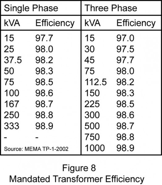
As of July 2006, the federal government has mandated, through the Department of Energy (DOE), 10 CFR-Part 431, that all low voltage, dry-type distribution transformers manufactured after January 1 2007 must have the minimum efficiency ratings shown in Figure 8.
To read part one of of the series, click here: http://library.automationdirect.com/transformers-application-construction-and-efficiencies-issue-15-2009/
By Brian S. Elliott
Originally Published: Dec. 1, 2010


1 Comment