Several years ago I purchased a Wadkin lathe made in England in late 1964. It is equipped with a very special motor that is 220V, three-phase and 50Hz. Because of the special design of the motor, it has a long extended shaft that carries the four sheave pulley, and because I do not have three-phase power in my shop, some means of creating it locally was needed.
I do have 220V power and the 50Hz design of the motor is not a problem. I knew about rotary phase converters and so called static phase converters, but neither really seemed to fit my needs. While doing my research of possible solutions, I learned about Variable Frequency Drives (VFDs). This seemed like the answer that I needed and further investigation showed that several manufacturers of new machinery were using three-phase motors/VFDs to provide better control over machine speed, soft start (programmable acceleration) and forward/reverse functions.
 I looked at several different VFD brands and found the ones from AutomationDirect best fit my application. I liked the keypad setup and the ease of programming the VFD for my lathe; also helpful is the ability to mount the keypad remotely with the optional extension cable. I even programmed the display to show actual spindle lathe RPMs.
After I had my lathe up and running and found how well the AutomationDirect VFD worked out, I decided to convert my Rock-well ram-type radial drill back to three-phase and install another VFD on it. Because this only has a ½ HP motor, I was able to use a VFD with 120V single-phase input and 220V three-phase output. Again I went with AutomationDirect and used a remote control for the forward/off/reverse and speed controls.
I had been experimenting VFD with the programming, changing things like the acceleration times, method of stopping, what the dis-play showed, and some of the other programmable functions. Once I became comfortable with the programming procedure, I found that I could customize the the VFD to my exact needs.
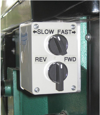
The remote controls that I used in both of these installations are simple to build and in fact, so simple that I called the support team at AutomationDirect to be assured that it was as simple as it looked. The support people were able to explain things in a manner that clearly answered my questions.
Issues with a Milling Machine
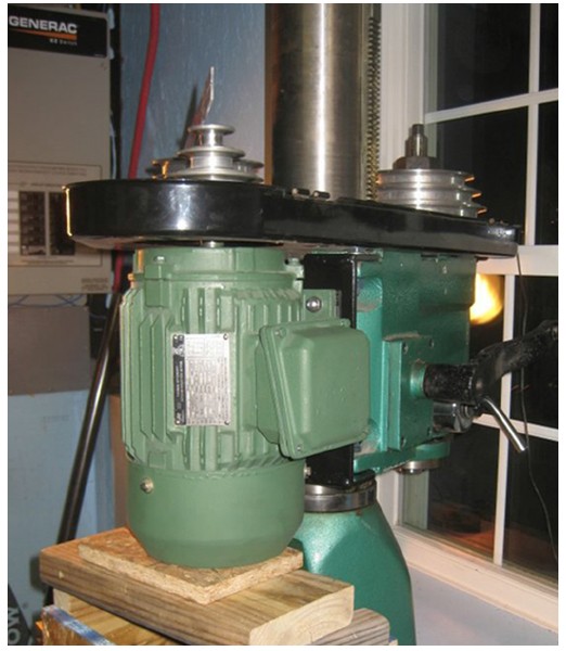 I recently purchased a mill/drill milling machine patterned after the popular Rong Fu model. I soon found that there were some issues with the machine that I felt could be corrected with the three-phase motor/VFD conversion.
Because it is a three-pulley, two-belt drive setup, with the center pulley acting as an idler with both belts on it, changing the spindle speed requires removing and changing the position of both belts. This is very time-consuming and inconvenient.
Also it had a capacitor start/capacitor run motor that, while powerful, was not smooth running. Another issue was a flimsy motor mount that kept bending. Replacing the motor and adding a VFD would provide electronic speed and reverse control, add soft start and a smoother running motor; it also gave me the opportunity to fabricate a stronger motor mount.
Materials Required to do the Conversion
In order to keep the same size motor (2HP), I used a chart to determine the proper NEMA frame size needed for the replacement motor. If you have a motor with a NEMA frame, then all you need to do is get a replacement with the same frame number and it will bolt right in without any modifications. The same NEMA frame size can have different horsepower, different base RPMs, and be either single or three-phase. The NEMA 145T model MTCP-002-3BD18 motor from AutomationDirect most closely matched the metric motor on my mill. Because I was replacing the motor mount anyway, the difference in mounting holes for the motor base was not a problem.
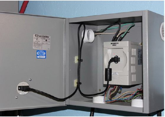
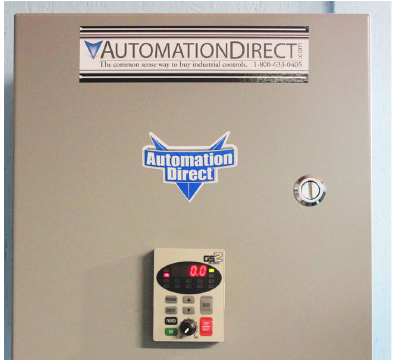
I chose to use the GS2-22P0 VFD from AutomationDirect rated with my 2HP motor. I also used the optional extension cable, GS-CBL2-1L, to allow mounting of the keypad on the outside of the door of the Hubbell-Weigmann N1C121208 steel enclosure.
For the remote control unit to be mounted on the mill/drill itself, I used an SA-106-40SL enclosure, a GCX1370-22 for-ward/off/reverse switch, and an ECX2300-5K potentiometer.
The cable that powers the VFD is a 12/3 SOOW SO cord and a 14/4 SOOW SO connects the VFD to the motor. To connect the VFD to the remote control, I used an 8-conductor 24-gauge Ethernet computer cable, run inside a piece of 3/8” flexible conduit for protection. (You only need six of the conductors for the remote.) These cables are readily available at www.automationdirect.com and most electronics stores.
The Installation
The first thing that needed to be done was to fabricate a new motor mount. I found the best way to mount the motor was to build a temporary platform for the motor and then lower the mill into position on the motor. I temporarily moved the old motor out of the way and with the new motor in position, determined the size of the new motor mount and the location of the mounting holes.
I used a piece of ¼” steel plate and welded on two ears for the hinge bolts. I then used the mill to machine in the four slots for the motor to ride and adjust in and drilled the hinge bolt holes. After applying a coat of paint, I was ready to install the motor.
The remote control box was mounted to the mill housing using a piece of 3” angle aluminum. This provided a very sturdy mount and placed the controls right up front where they are easy to reach.
The VFD unit is mounted inside a wall-mounted steel cabinet behind the machine. It is close enough so that the display can be read easily and the unit programmed using the keypad.
The VFD generates a small amount of heat, so I installed four soffit vents with a fine screen inside. There are two on the bottom and one on each side near the top which allows for air flow within the closed cabinet.
When connecting the power cables, it is best to use crimp-on connectors because the connecting screws on the VFD are relatively small. The control cable can be connected directly if you tin the ends of the wires. Tinning the ends makes it easy to insert the wires into the terminals on the switches and the VFD and prevent them from becoming crushed by terminal screws.
You need a means of disconnecting the unit from the power source and it should be protected with a circuit breaker. The electric panel is about 5 feet from the VFD and it is on a dedicated circuit, so my means of disconnecting is a plug on the end of the power cable and a twist lock outlet. When it is unplugged, I know it is disconnected.
The keypad is removed from the VFD unit by squeezing the two tabs on the sides and pulling out. The cabinet door needs to have three holes drilled to accept the keypad.
Programming the VFD
After all the components are installed and the power and control cables are hooked up, the next step is programming the VFD to set up the parameters for the particular installation; detailed programming provides the maximum benefit and performance from the VFD.
The VFD comes with a “Quick Reference Card” and a user manual. Both list the parameters used in programming the VFD. The information shown on the motor data plate is the first item to input. Once the scheme for programming is understood, it becomes easy to customize the VFD to your particular needs. The programming mode is entered by pressing the “Program” key on the keypad. Selections are started by pressing the “enter” key and changes are entered using the “up/down” arrows on the keypad, followed by pressing the “enter” key to save the selection.
The four most commonly used programming sections include: motor data, motor control, remote control activation and display customization.
Programming section “P 8.00” is the display function. There are many options here. I like to use one that shows the spindle or cutter speed in RPMs. This is accomplished by entering “02” which shows the output frequency multiplied by a factor. That factor is the spindle speed divided by the output frequency. This can be determined several ways. One way is to use the specifications for the machine which will show spindle speed with the standard motor speed.
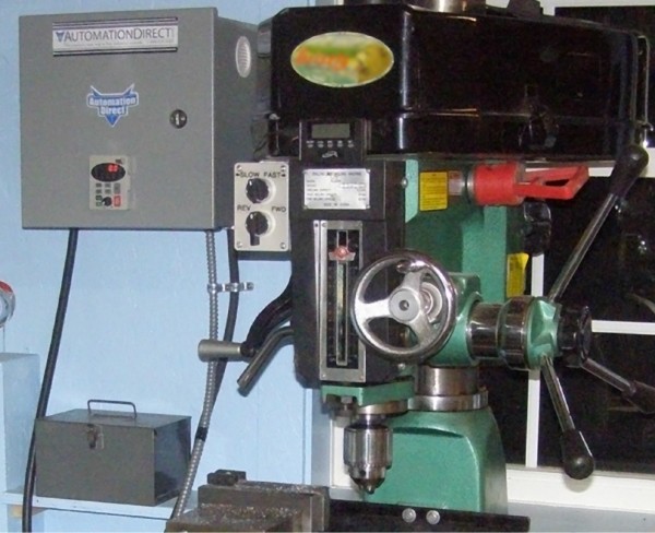 Another way is to use a tachometer to measure the spindle speed at a given frequency. I used an inexpensive digital tachometer to determine the spindle speed at 60Hz and found it was 485 RPMs. 485 divided by 60 gave me 8.08 which I entered at “P 8.01”. The display now shows actual spindle speed for my particular belt and pulley configuration. If using multiple belt configurations and you have a chart showing the speed for those at a given motor RPM, changing the display to show percentage of RPM works nicely. This is achieved by changing the value to 1.66.
This installation was on a mill/drill, but the same procedure would be used on most any machine used in a woodworking or machine shop.
The power from the VFD would go to the three-phase motor and the remote control would be mounted in a convenient location and you are ready to go.
The most important rule for sizing the VFD to the motor is that the VFD needs to be rated at least as large as the motor. If you were using a VFD on a machine such as a table saw, planer, grinder, etc. then the Reverse function would be disabled by using an Off/On switch and only connection to the “D11” terminal on the terminal strip. If the motor runs in reverse when you want it to go forward, swapping any two of the power leads from the motor to the VFD will correct this.
For many years, woodworkers thought that the only way to use three-phase machinery was to have three-phase power from the electric company or use an expensive and inefficient rotary converter or a static converter that only allowed the motor to operate at 2/3 of its rated output. For motors up to 3HP, modern VFDs have the ability to take single-phase electricity, convert it to three-phase with full power, speed control, reversing ability, and more.
The VFD is really a “game changer” for anyone restoring old machinery or dealing with methods of speed control, such as Reeves drives and variable diameter pulleys. The VFD is truly “a better way.” I have three in my shop now and have plans to install two more very soon.
To read more about variable speed drives, click here, about enclosures click here, about motors click here.
Originally Published: Sept. 3, 2015


