By Michael Probst, BSEE ’22
The Georgia Institute of Technology Engineering Department requires two semesters of design experience, with a course known as “senior design”. Students divide themselves into teams of 4-6 students, often comprised of members from within a single department, or students can form interdisciplinary teams. The projects themselves come from three sources: faculty proposed, industry proposed, and student proposed. At the end of the two semesters, teams from every school in Georgia Tech present their projects at the Georgia Tech Senior Design Expo. Judges with industry experience review the designs and select winners from each school.
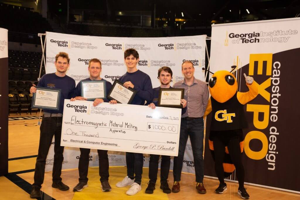
My team consisted entirely of members within the School of Electrical and Computer Engineering (ECE): Benjamin Bogard (EE), Dakota Cobb (EE), Nicholas Meyer (CompE), Michael Probst (EE), and our faculty advisor Dr. Lukas Graber (ECE). Of the 20 teams competing in the ECE category, our student-proposed project won the prize (and a $1000 cash award) for Best Design.
Overview
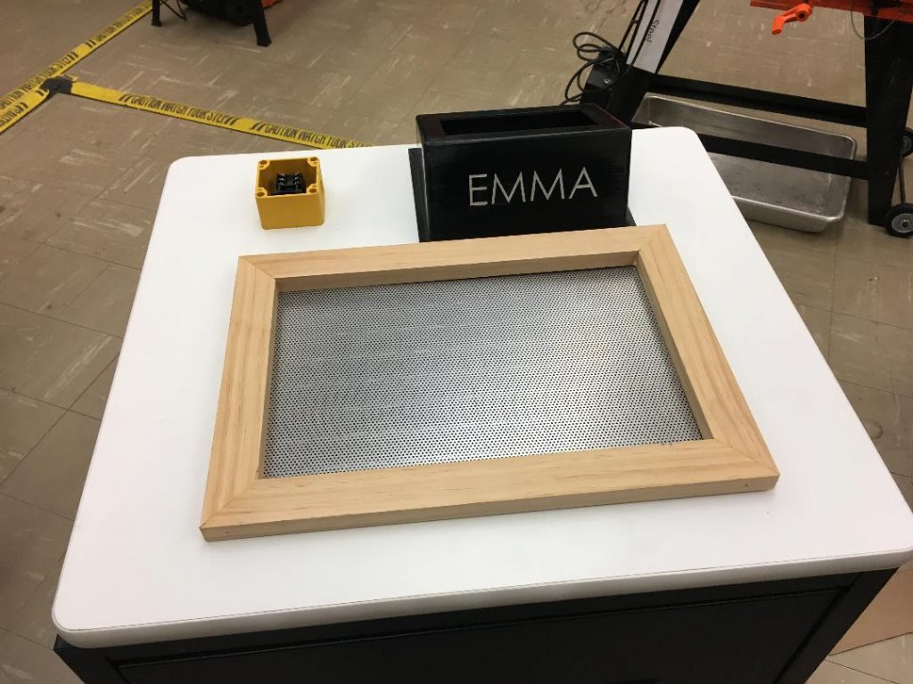
Our project is a 10 kW induction furnace: a device that converts electrical energy into heat to melt metal. We affectionately named it EMMA, the Electromagnetic Material Melting Apparatus in honor of our first choice of project. We originally proposed an Electromagnetic Metal Accelerator (EMMA), but were told getting permission to build a coilgun would be prohibitively difficult, so we settled for metal melting instead.
The utility of induction heating is fourfold: decreased waste, increased efficiency and portability, and the removal of a fossil fuel source.
- Decreased waste. Traditional gas burning furnaces often produce chemicals that are harmful for the environment or the operator. The induction furnace itself does not produce any chemicals, airborne or otherwise. If a pure metal is being melted, anyone can stand right next to it without breathing anything toxic.
- Increased efficiency. Again, traditional gas burning furnaces operate at ~30% efficiency. Our furnace only loses energy as the electrical components heat up during operation. Even running without the water cooling system active, the components barely rose above the ambient temperature. We estimate the furnace operates at 90-95% efficiency.
- Increased portability. The entire furnance fit in a 4’ steel enclosure on wheels. We easily transported it from our lab to a truck and across campus to the exposition.
- Removal of a fossil fuel. Instead of connecting a gas line or using temporary propane tanks, our furnace is electrically powered.
Hardware Components
The fundamental principle of the EM furnace is that things get hot when you put a current through them. In simple terms, the furnace puts a large current through a piece of metal and it heats up like any other resistor. The control challenge is then a power electronics problem: How do we deliver a large current through a workpiece from a wall outlet? Though it would be pretty cool, we cannot simply wire a piece of metal to a wall outlet because the metal eventually melts which would also melt the connection. The solution is to use high-frequency AC power and several transformers to transfer the energy to the workpiece via a magnetic field. This galvanically and physically isolates the workpiece preventing ground loops and evading the need for a physical connection respectively.
Starting at the power entry, we chose a 208 Volt 3-phase 60 Hz power source with a 30 A maximum current draw because a standard 120V single-phase wall outlet would not give us sufficient power. The first step was to convert the 3-phase power into a DC waveform, which we accomplished using a 3-phase diode rectifier and large capacitor for smoothing. Then, we slice the DC waveform into a high-frequency AC waveform with two half-bridge insulated-gate bipolar transistors (IGBT’s). The IGBTs act as switches that reverse the polarity of the waveform several thousand times a second to produce the required AC waveform.
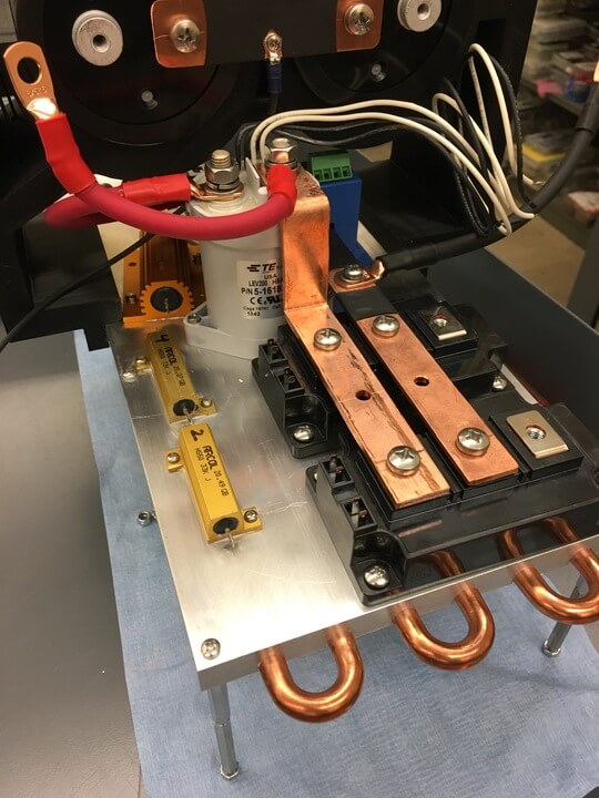
The next stage of the power electronics is an RLC circuit which ultimately transfers power into the workpiece. We connected a power capacitor, a large coil, and the workpiece in series acting as the capacitor, inductor, and resistor respectively. In the AC domain, the capacitor and inductor have a reactance, a frequency-dependent resistance. The capacitor’s reactance decreases with the frequency and the inductor’s reactance increases with the frequency. Further, the reactances have opposite signs. Therefore, there is a frequency, known as the resonance frequency, where the capacitor’s reactance is equal and opposite to the inductor’s reactance. At resonance, the two reactances cancel, driving 100% of the energy into the workpiece.
The capacitor and inductor are necessary for two reasons. Firstly, the workpiece sits in the coil so the metal does not have to be physically touching the coil but still has heat transfer. Therefore, we can place the workpiece in a crucible located in the middle of the coil and transfer all the energy through the air into the metal. Secondly, by operating slightly off-resonance, we can limit the power draw. For example, if the breaker only supports 10 or 15 A, we operate slightly above or below resonance to draw less power.
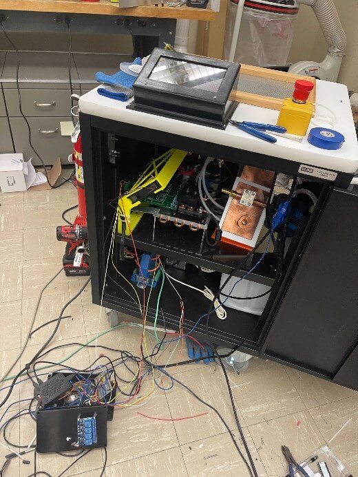
The electric components were cooled by a water cooling loop complete with a radiator, deionizer, and a 3-gallon reservoir. Some components had inherent water cooling capabilities and others were mounted to a cooling plate. We assembled the entire device in a wheeled steel enclosure and constructed a firebrick platform to the side as a work area.
AutomationDirect Components
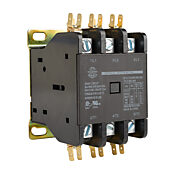
3-Phase Contactor (WDP60-3L-120)
The 3-phase contactor is controlled by a microprocessor and allows us to power up and power down the device by isolating the power supply from the rest of our components.
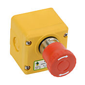
Emergency Stop Button (ES-P-230001)
The control signal to close the 3-phase contactor was wired in series with the emergency stop button. By hitting this button, we can shut down the power to the device in the event of a failure such as over current, over temperature, or overvoltage.
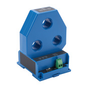
3-Phase Current Transducer (3ACTR100-42-24-F)
We use the 3-phase current transducer to monitor the power draw of the device. We can then determine if we are on or off-resonance and adjust the frequency for maximum power draw.
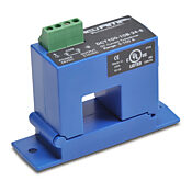
DC Current Transducer (DCT100-10B-24-S)
Like the 3-phase transducer, the single-phase transducer was used for power calculations. We use this to ensure the rectifier stage of the furnace is functioning properly. Multiplying the current by the DC voltage is the current power draw of the device.
Software Components
We added a significant software component to the furnace which performs several functions used during operation. At the user interface, there is a touchscreen that is driven by a Raspberry PI. The real-time operating system of the furnace is controlled by an ESP-32; an off-the-shelf low-cost, low-power, system-on-a-chip microcontroller with integrated Wi-Fi and Bluetooth. The power-up and power-down procedures of charging the DC link capacitor and the operating frequency of the IGBTs are controlled by the ESP-32. The user interface is configured for temperature, current, and voltage monitoring of the device and has buttons to charge and discharge the capacitors.
Wrap-Up
At the Georgia Tech Senior Design Expo, we performed a low-power demonstration by heating a steel wrench until it was visibly glowing cherry-red. For our demonstration, we received the prize for the best design in the School of Electrical and Computer Engineering.
Read more here: https://www.ece.gatech.edu/news/653554/students-overcome-turbulence-shine-capstone