Ethernet is the most widely used network in industrial plants and facilities, here’s a primer covering its foundational concepts.
By: Bill Dehner, AutomationDirect
Ethernet was first conceived and deployed in a research setting in the 1970s and was soon standardized in the early 1980s under IEEE 802.3. This quickly led to commercial adoption in office environments, usually to network business PCs. Since its evolution, Ethernet has undergone many upgrades and improvements, making it the world’s leading wired network technology not only in offices, but also in industrial plants and facilities. The use of Ethernet in these industrial environments will be the focus of this article, although much of the information is also applicable to commercial Ethernet installations.
Ethernet Everywhere
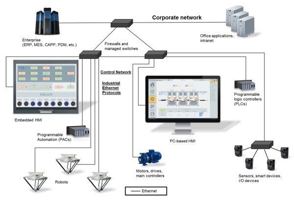
Industrial sites today commonly use Ethernet to connect PCs, programmable logic controllers (PLCs), remote I/O, human machine interfaces (HMIs), smart instruments, motor drives and other intelligent automation components (see Figure 1). PCs are commonly used to host HMI, asset management, enterprise resource planning, production planning and other applications.
Several other mission-specific, and sometimes proprietary, industrial networks have also been developed over the years. However, these are generally implemented at a lower level in the automation system hierarchy than Ethernet, and offer specialized features such as power delivery, extended physical range and noise immunity. These specialized networks will not be addressed in this article.
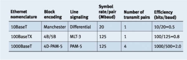
Exponential speed improvements have been a major component of Ethernet’s evolution. As shown in Figure 2, there are currently three versions of Ethernet: 10BaseT, 100BaseTX (also known as Fast Ethernet) and 1000BaseT (also known as Gigabit Ethernet because it transmits Ethernet frames at a rate of one gigabit per second). While some details vary among these versions, the most important differences are speed and cost, with cost increasing along with speed. While consumer hardware and PCs typically operate at Gigabit speeds, most modern industrial Ethernet installations and components use Fast Ethernet.
What are the Different Types of Ethernet Cabling?
The first point to consider when deploying an Ethernet network is the type of cabling. Cat5e cable supports Gigabit speeds and is often the minimum specification recommended. Also available is Cat6, providing better performance at a higher cost, and also providing a degree of future-proofing as Ethernet moves toward 10 Gigabit speeds in coming years. Although commercial installations use unshielded cables, shielded cable should be used in industrial environments to protect from electrical noise generated by motors, motor drives, welding, and other electrical equipment.
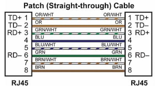
In years past, it was important to define whether cables should use straight-through patch or crossover connections (Figure 3). Crossover cabling was typically required when directly connecting components to each other, and patch cabling was used when connecting components to Ethernet IT devices such as switches and routers.
However, most devices today support Auto MDI/MDIX which will accept either configuration, so most installations use patch cabling throughout. As shown in Figure 3, RJ-45 connectors are used for most Ethernet connections.
Another point to consider for both performance and compatibility is communication speed, and half or full duplex capability. While duplex compatibility can be overcome by using a managed switch or router—discussed in more detail later—performance is limited to the slowest device.
As previously mentioned, Fast Ethernet is used in most industrial automation applications because its raw speed is more than sufficient, but this can be affected by the selection of half or full duplex. With half duplex, a device can only transmit or receive, but can’t do both simultaneously. This reduces performance, and in the worst case half duplex devices drop packets under heavy load due to data collisions.
Most components and devices used in Fast and Gigabit Ethernet installations therefore use full duplex, meaning the node can transmit and receive simultaneously.
What are MAC Addresses and IP Addresses?
The media access control (MAC) address is the hard, physical address of a component or device. The address is set during manufacturing and should never change. Although there are exceptions to this, hard coding the MAC address was the original intent of the design. An Ethernet packet cannot enter a component or device without this address. However, it’s rare that a communication setup or configuration will require entry of this address because another protocol, called address resolution protocol (ARP), usually automatically retrieves it and correlates it to an Internet Protocol (IP) address.
The IP address is the logical address of a component or device, used to identify its address and network. An IP address, such as 192.168.070.001, includes two identifiers: the network address and the host address. The network address helps switches and routers determine where to send messages. The host address identifies the specific component or device on that network. The subnet mask determines which part of an IP address is the network address and which part is the host address.
The default gateway address and a router enable connections to other networks. A component or a device can only send and receive Ethernet messages to other components and devices on its network as determined by the IP address and subnet mask. If a component or device needs to communicate with a component or a device on another network, a router is required. In order to get the message to the other network, the components or device will send its message to the default gateway address, which is the IP address of the router.
Local area network (LAN) and wide area network (WAN) definitions vary greatly, but in general LANs are networks encompassing switches and hubs. Once a network is divided into groups using a router, these networks are considered to be encompassed within a WAN.
What are Ethernet Hubs, Switches and Routers?
There are a variety of Ethernet network topologies including bus, ring and star. Bus and ring are similar to a daisy-chain connection, with a single cable hopping between each device. Bus topology is a bit obsolete, while the newer ring topology adds fault tolerance. However, most industrial Ethernet installations use star topology, with some ring connections to reduce cable run distances or improve resilience.
With the star topology, many devices connect to the central access point, the switch. Ethernet switches come in both unmanaged and managed configurations. There are applications and situations that make sense for unmanaged switches, and there are others where a managed switch is a better choice.
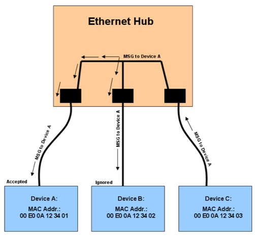
An Ethernet hub simply connects Ethernet devices together with no regard for MAC addresses, so all messages are sent to all devices (Figure 4). An unmanaged switch is a little smarter, using the MAC addresses to determine what components and devices are connected to each of its ports, and then routing messages targeted to those components and devices out the appropriate port, preventing the collisions often occurring with an Ethernet hub.
A managed switch adds features to those offered by an unmanaged switch, with one of the most important being selection of speed and duplex mode. When connecting a component or device to a switch, it must auto negotiate to an agreed-upon speed and duplex mode.
Auto negotiation is common in commercial environments but can fail for industrial situations. In these applications, it is often better to turn off auto negotiation, and use a managed switch to set the speed and duplex mode to a known working setting for both sides. This can be particularly helpful when connecting together components and devices from different manufacturers.
For a simple network with five or fewer components or devices in a relatively small area, an unmanaged switch will usually work, and it will always be less expensive than its managed equivalent.
For larger applications with more components and/or devices from several different manufacturers, a managed switch should be strongly considered. The benefits of a managed switch’s configuration and other features will easily outweigh the cost premium over an unmanaged switch in most complex applications.
A router is a more powerful version of a managed switch, with the ability to create different groups of components and devices within an Ethernet network. Creating groups allows one part of a network to be separated from another, a useful feature for managing network traffic. A virtual private network (VPN) router should be used when connecting a network via the Internet to provide the required degree of cybersecurity.
What are Ethernet Protocols?
The discussion so far covered some of the physical or hardware aspects of industrial Ethernet, but this is only half the story, with the other half being the many different software protocols used in industrial Ethernet installations.
Most industrial Ethernet protocols can run on standard Ethernet hardware, but some require modified and proprietary versions of hardware to operate. This is usually done to improve performance in highly specialized applications and these protocols won’t be discussed in this article.
Different industrial Ethernet protocols running on standard Ethernet hardware can all use the same network but can’t communicate with each other. The two leading industrial Ethernet protocols are EtherNet/IP and Modbus TCP. A standard Ethernet network could in theory have both of these protocols running on it simultaneously, but in practice it’s better to limit each network to one protocol.
To simplify, a protocol allows every device on the network to use a common language for communication. To understand this subject more deeply, it’s necessary to look at the Open Systems Interconnection (OSI) 7 layer model for Ethernet communications.
What is the OSI 7 Layer Model?
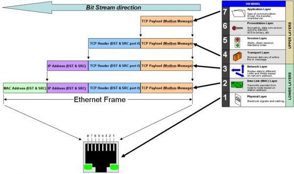
Figure 5 shows the model divided into upper and lower layers. Most industrial Ethernet protocols will not use all 7 layers. Figure 6 shows how Modbus TCP fits into the model, using Layers 1-4, and Layer 7. The goal for protocols adhering to this model is for any network-connected device to be able to transmit a data packet or message to any other device.
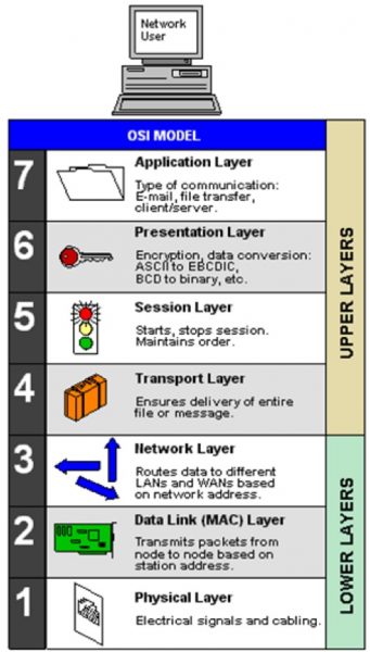
As previously discussed, every Ethernet device carries a unique MAC address and must be assigned an IP address compatible with the local Ethernet network port it is connected to.
Messages initiate at a device connected to Physical Layer 1, which has already been discussed in terms of its electrical signals and cabling. The Data Link Layer 2 is the next one up, acting as a traffic cop in the form of Ethernet switches and other Layer 2 devices. These devices use the MAC address of each component or device to figure out which packets go to which ports, and strip off the MAC address in the process. Similarly, network layer 3 uses the IP address to route the data packets. Finally, transport layer 4 delivers the data payload, the actual Modbus message for Modbus TPC, up to layer 7.
Layer 7 is the Application Layer, and this is where a common language is important. Although other industrial Ethernet protocols may be identical to Modbus TCP in their use of layers 1-4, and can thus use the same network, they won’t be able to communicate with each other because their application layer 7 is different.
What are Unicasting, Broadcasting and Multicasting?
Unicast messages are sent from one specific device or component to another. Broadcast messages are sent from one device to all components or devices in a group. Multicast messages are sent to many different receivers at once, typically all components or devices on an Ethernet network. The groups associated with Ethernet networks are created by a router.
A router is needed to make sure a broadcast message only goes to members of a group, but managed switches can intelligently route multicast messages to the correct ports of all components or devices on a network. A managed switch will learn which ports should be receiving multicast messages, using a feature called IGMP Join, and only send messages to those ports, resulting in significant performance improvement.
Managed switches can also prevent a network from shutting down if someone accidently connects switches into a ring. If unmanaged switches are mistakenly connected together in a ring, then messages will continue to propagate, creating a broadcast storm which will overwhelm and shut down the network. Managed switches prevent this by shutting down one path of the ring. If something happens to the working path, the switch changes over to the other path, which also provides a level of redundancy.
There are many more details not covered in this discussion of Ethernet basics. Please see the list of references for further details regarding industrial Ethernet.
References
1. Design World Mar 2017, Ethernet From the Ground Up
2. Ethernet Dos and Don’ts
3. Control Engineering Jun 2016, Ethernet As a Leading Machine Automation Protocol
4. Design World May 2016, Applying Industrial Ethernet
5. Industrial Ethernet Book Oct 2015, Real Time Protocols