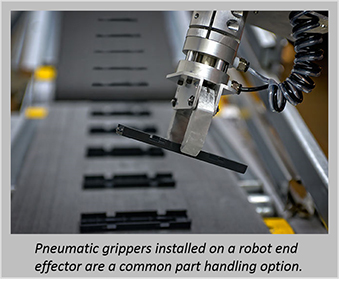
Pneumatic actuators are a popular option for parts handling in automated systems. Whether it’s part transfer, positioning or clamping—pneumatics are a cost-effective choice for mechanical motion. However, without proper design, these pneumatic systems can experience problems. Fortunately, there are some simple pneumatic design guidelines to help ensure success.
We’ll review some common issues with pneumatic designs, and discuss best practices to help improve your odds of success.
Common Issues
There are some leading problems areas to look out for when designing a pneumatic system, including:
-
-
- Low or varying air pressure
- Improper use of flow controls
- Cylinders bang at power up
- Pneumatic actuators not dumping air properly
- Slow or inconsistent cylinder speed
- Loud pneumatic actuation
- Sticking or leaking solenoid valves
-
Getting the air pressure right is the first step. Varying or improper air pressure can cause inconsistent pneumatic actuator motion. Flow controls, or lack thereof, can also adversely affect motion. Improper flow control component selection can make an actuator move too slow, even with the flow control wide open, and removing flow control can literally hammer the end off of a pneumatic cylinder.
A cylinder can also bang at power up, and this motion is often very rapid and can be dangerous. Not dumping air during an emergency stop or power off situation can also be dangerous, as the stored air can cause unanticipated motion when equipment is re-energized.
Slow or inconsistent cylinder speed is also a common problem. Too little flow or low air pressure is the obvious culprit, but other issues to watch out for include an oversized cylinder, and undersized solenoids or air lines.
Although loud pneumatic actuation may be due to one of the several design issues discussed above, it could also be caused by not having end-of-stroke cushions built into the cylinder. Leaking valves can also cause sluggish actuator response.
Best Practices and Design Guidelines
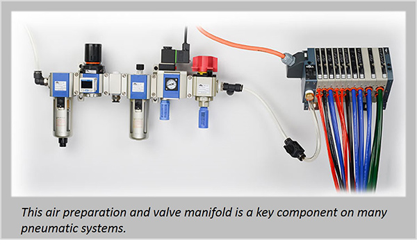
A properly designed pneumatic system starts with adequate plant supply and an appropriately sized air preparation system. The plant supply should provide proper flow and the air pressure should be consistent. Dynamic demands placed on the plant air supply can cause machine variations, so be sure to have a large enough supply line, and use an air accumulator if necessary.
Here are some other best practices:
-
-
-
- Use a manual, lockable air dump valve
-
- Use a filter regulator
-
- Use an electric soft-start air dump valve
-
- Don’t oversize the cylinder
-
- Use flow controls
-
- Specify cylinders with built-in cushions
-
- Use mufflers for noise control
- Use lubricators only if necessary
-
-
All machines should include a manual, lockable air dump valve and filter regulator. Although disconnecting air using a quick-disconnect can make the machine safe, the quick-disconnect could be inadvertently plugged back in. A manual lock out valve protects against this by including a locking point.
Installing a filter regulator just downstream of the plant supply line sets machine max air pressure, a good idea since plant air supply could be in excess of 120 psi. This high of pressure is unnecessary in a properly designed system, and can cause issues. In addition to regulating pressure, the filter regulator keeps the air clean and can remove water.
An electric soft-start air dump valve is an important safety feature. This electrically-actuated device quickly dumps air when power is removed, placing the machine in a safe state during an emergency stop or guard door open condition.
Not only is the soft-start required for proper operator safety, some systems require dual valves and air pressure monitoring to ensure safe removal of motion. When a machine is re-energized, the soft-start valve acts as a flow controller to slowly re-pressurize the pneumatic circuits.
The properly controlled and prepped air supply connects to solenoid manifolds with 4-way or 5-way valves. Don’t skimp on valve size or the cylinders will operate slowly. Even with appropriately sized valves, the cylinder may still move slowly if the cylinder is not sized properly. Bigger is not necessarily better when it comes to cylinders.
Your cylinder supplier has calculation tools to help you size the cylinder based on the work required and the machine cycle time.
The cylinders should also include flow controls for speed regulation. The flow controls typically control the flow of air exiting a cylinder, which regulates the speed of the cylinder. Many properly sized pneumatic cylinders will move too fast, causing slamming and banging of cylinders. This can cut cylinder life, even if built-in cushions are included in the cylinder to provide a quiet, low-impact stop. Flow controls slow actuation, which is good practice for extended life and safety. And while pneumatics and cylinder motion can be loud, mufflers can be added to the exhaust ports on valves and manifolds to greatly quiet the system.
A final item is lubricators. Most systems don’t require them, and it’s best to not use them as they create oil mist when exhausting lubricated air. But, this is dependent on system design, and in some instances lubricators may be needed.
For more information, please see the article Pneumatic System Guidelines for Success in the October 2015 issue of DesignWorld’s PneumaticTIPS.com, authored by Pat Phillips, a Product Manager at AutomationDirect.
To learn more about pneumatics check out our other articles here. 


