Pneumatics have been used in industrial machines and manufacturing plants and facilities for decades, so most of the basic components are tried and true, with significant innovations few and far between. But there are many innovative ways to combine these different components to create pneumatic subsystems.
The explains four pneumatic subsystems, showing how combining basic pneumatic components in novel ways improves operation, maintenance and safety.
Table 1: Basic Pneumatic Subsystems
- Air preparation
- Double-acting cylinder
- Continuous cycling
- Two-hand control
Air Preparation Subsystem
A single-point pneumatic air connection should be used on most automated machines, starting with an air preparation subsystem. Its components are listed in Table 2.
Table 2: Common Air Preparation Subsystem Components, Figure 1
- Manual shut-off relief valve, VLV01
- Filter, FIL01
- Regulator with gauge, REG01 and GUA01
- Soft-start/dump valve, VLV02
- Pneumatic distribution block, not shown
- Lubricator, if needed, LUB01
Philips notes that it’s often advantageous to buy these components pre-assembled into a single unit.
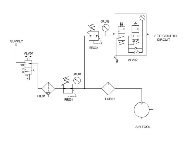
A fairly recent innovation is combining some or all of these components into one unit, which can be purchased from AutomationDirect with a single part number. This is often much more convenient and cost-effective than buying individual components and assembling them into a unit.
This air preparation circuit, often called an FRL (filter, regulator, lubricator), is commonly used on many machines, and its use is recommended as a good design practice.
The clean, filtered air exiting the first regulator is split through a pneumatic distribution block, not shown on the diagram, to supply an unlubricated and lubricated air supply. The electrically operated soft-start/dump valve is usually the last device before air cylinders, actuators and other motion-causing pneumatic devices, which typically don’t need lubrication. It provides a means to dump motion-causing air pressure when an emergency stop is activated. A lubricator is often installed in the air supply line to air tools.
Double-Acting Cylinder Subsystem
Figure 2 depicts a 4-way solenoid valve (SOL01) controlling a double-acting cylinder (CYL01). This is one of the most common pneumatic functions on an automated machine controlled by a PLC. The air supply to the solenoid has already been filtered by the air preparation unit.
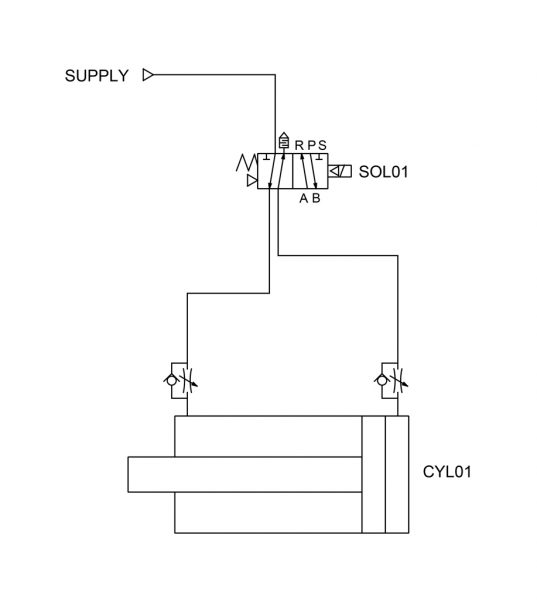
Double-acting cylinder circuits are typical on many PLC-controlled machines.
Philips says to watch the specs:
The valve solenoid symbol indicates a single-acting, spring-return valve. The triangles in each side of the valve indicate it is pilot-activated as well. While this pilot air makes the valve more efficient, it also requires a certain amount of pressure. For example, supplying less than 20 psi can stop the valve from functioning, so users should check the valve specifications for minimum operating pressure.
Continuous Cycling Cylinder Subsystem
Figure 3 illustrates how pneumatic components can be combined in an innovative fashion to create a continuous cycling cylinder. No external controller is required with this novel design, just compressed air supplied to valves VLV02, VLV03 and VLV04.
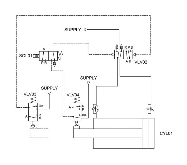
This continuous cycling cylinder circuit shows some of the control capabilities of pneumatic components
Key components for this pneumatic logic are the 4-way air-piloted valve (VLV02) and the two 3-way roller-actuated valves (VLV03 and VLV04). Instead of springs and electrical solenoids controlling the position of the valve spool, air pilot pressure alone operates VLV02. The roller-actuated valves, configured like the mechanical arm on a limit switch, actuate VLV03 and VLV04, each of which is spring-returned when not actuated. Cams or flags on the cylinder actuate the valves.
Two-Hand Control Subsystem
Figure 4 depicts a two-hand safety control circuit for a press application. This circuit provides a good example of the inventive use of manual 3-way valves (pneumatic buttons, VLV01 and VLV02), and an air-piloted 4-way valve (VLV03). The design of this circuit allows small manual valves to operate a large pilot-operated valve with high air flow requirements to drive a large press cylinder.
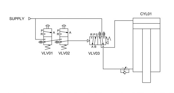
This two-hand control circuit shows how manual pneumatic buttons can be used to improve safety when operating heavy machinery such as a press.
This is a very safe circuit, Philips points out:
The design of this circuit requires the operator to press both buttons simultaneously. Once this is done, pressure is cascaded through the two hand valves, supplying pilot air to actuate the 4-way valve. When activated, the double-acting press cylinder (CYL01) extends. The use of a 4-way, spring-return valve retracts the press cylinder when either button is released to its normal, relaxed position as air is supplied to the retract side of the cylinder.
These four pneumatic subsystems show some of the functionality available by combining common pneumatic components in innovative ways. Additional combinations can be used to create other subsystems, limited only by the imagination.

Pat Phillips, Product Manager for the Fluid Power and Mechanical Product Division at AutomationDirect, wrote an article that ran in the June 2018 issue of Fluid Power World titled Innovative Pneumatic are Realized in Subsytem Design.
To read more articles about pneumatics, click here.