For a better understanding of PLCs, let’s take a closer look at one of the fundamentals of automated control – logic circuits. Electrical components can be hardwired in a way to allow certain decisions to be made electrically. They can provide physical “If, then” statements that systems can use in their decision making. “If this event occurs, then do this” or “If X and Y are ON, then turn on Z” decisions can be accomplished with hardwired circuits. The most common logical circuits in automation are the AND and OR circuits, accomplished with series and parallel wiring configurations.
Logic Circuit Must-Haves
You can easily configure an AND circuit by wiring two switches or contacts in series, providing only one path for current to take. Take the output point from one switch and wire it to the input point of the other. The output of this circuit can then be used to turn on a light, fan, pump etc. By doing this, you are telling the end device to wait for BOTH conditions to be met before activating. In the case of pump control, one switch contact could be from a float level switch placed toward the bottom of a tank, and the other from a START pushbutton on an operator’s panel. Both the command to start (from the operator) and the pump having sufficient water (from the float switch) must be true before the pump can start.

EITHER-OR
To create an OR circuit, use a parallel configuration with the switches so that current has more than one route to take. Wire the input points of the two switches to the same source and the output points to the same end device. For our circuit, let’s add another way for the pump to start. We want the pump to also start automatically if the level inside the tank exceeds a certain height indicated by another float switch mounted higher up in the tank. By placing this contact in parallel with the manual start, we have now given the circuit a choice of start commands – manually by the operator OR automatically by the upper level switch.
WORKING TOGETHER
If we now take the two circuits and combine them, we will have a combination AND/OR logic circuit. Either start method can still be used to start the pump but they are now both dependent on the AND contact. Neither start methods will work unless the low-level switch is in the correct state. In other words, if the tank level is sufficient AND either the operator commands it, OR the tank level exceeds the upper limit, then the pump will turn on.
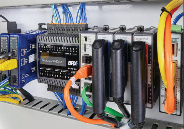
PLCs are used to perform the exact same logic as logic circuits but without the need to hardwire these components together. Instead, by wiring these components to the PLC, the PLC will perform the logic for you and turn on/off the outputs or end devices as needed. This is extremely convenient especially if the need arises to change the logic to include more inputs and/or outputs. PLCs can also perform numerous other logical functions with these components that physical wiring alone cannot accomplish.
For more on this and many other PLC topics, visit our FREE Online PLC Training Portal to take advantage of Interconnecting Automation’s online PLC video training series.

To read more articles about PLCs, click here.
Originally Published: January 2019