Automated Integration replaced many relays, an old PLC and what seemed like miles of wire when it upgraded the control and safety system on the Hurricane roller coaster in New Mexico.
By Manny Salazar, Manager, Automated Integration, LLC.
The Hurricane roller coaster was purchased from the Santa Cruz Boardwalk in California, where it was originally installed in 1992. From there, it was disassembled, placed on 12 semi-trucks, and transported to Western Playland Amusement Park in Sunland Park, New Mexico. It took about a month to sand, paint and reassemble the roller coaster at the amusement park, where it was re-commissioned in late spring of 2015 (Figure 1).
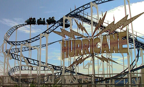
The steel track, Windstorm and Twister type coaster is quite a thrill to ride. It is approximately 55 feet tall, and the original specifications indicate the cars can reach 50 to 60 mph on the track and exceed 4 G around turns. The ride consists of two 12-passenger trains with three 4-person cars each. With nearly 1500 feet of track length, the ride time is approximately 50 seconds.
After it’s recommissioning in 2015 at its new location, the ride was very unreliable and difficult to maintain with intermittent problems. It was constantly breaking down, and the control system was very difficult to troubleshoot and repair, with many parts obsolete. Automated Integration (www.automatedintegration.net), a local system integrator, was contracted for this retrofit project to replace the coasters failing control system. There were many relays and much related wiring, along with a very old Siemens S5-100U PLC that needed to be replaced.
Automated Integration provides a variety of automation design, maintenance, repair and programming services. It has a broad customer base in oil refineries, water utilities, food processing, HVAC building control, manufacturing and communication systems. It provides controls integration and programming services to many companies. If a project has any level of automation using controllers, relays or similar equipment, Automated Integration can likely service and support it.
Failing Relays Cause Intermittent Faults
The entire control system was failing. It was a mess and the ride would not run reliably. Sometimes the chain drive used to pull the coaster to the top of the first hill would shut down. Sometimes the safety interlocks for the cars would fail, stopping car movement. The sensors used to determine speed and car position around the track were failing as well. For example, the sensors would fail to indicate a car was in the correct position to begin the ride, inhibiting the control system from starting the ride. The failures were numerous and were occurring more frequently.
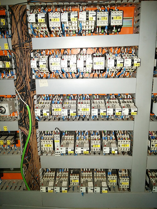
The original control system was based on relay control, not a surprise considering is was designed, built and installed in 1992. There was a small Siemens S5-100U PLC used for braking functions, but this PLC was not fully operational because it had been bypassed in places by the previous owners.
One of main problems with the design was too many relays interconnected to other relays for operation (Figure 2). There were many complex, hardwired circuits. One relay in a chain would fail, sometimes intermittently, and a fault would occur, but it would be difficult to find the cause of the fault. It was a frustrating control system to support, with the intermittent faults the worst of many problems.
Sequence of Operation
The ride sequence requires two sets of cars (trains) to alternate. When in automatic mode, the system is run with one start button and one forward button on the last zone of the ride. The ride can be started with a loaded train in the start (loading) area and an empty train in the unload area, immediately upstream of the start.
The start button is pressed and the 3-car train is released. The chain drive drags the train to the top of the hill where it runs free and coasts until the last zone is reached. The last zone is the unloading area. Once the loaded train clears the start area, the empty car can be sent forward and is ready for new riders to board.
The braking system was previously an all pneumatic system operating friction brake pad mechanisms at appropriate points in the ride. The new design still uses pneumatic brakes in several locations, but a few were replaced with magnetic brakes which require no external control, just adjustment to slow down the train at key points of the ride. The starting and endpoints still have pneumatic brakes, as well as electromagnetic brakes within the motors themselves.
Upgraded Control System
An AutomationDirect CLICK PLC was chosen to replace the old PLC and many of the relays. The PLC is used in a “dual-rack” configuration and controls all ride operations. It also controls the air compressor system and braking systems, and monitors the position of the trains in the ride.
The PLC monitors positions of the train cars, and determines whether to allow them to proceed to the next station (blockzone) in the ride.
All the compressed air system monitoring was replaced with new pressure switches, and programming in the new PLC was added to monitor and verify all pneumatic and electromagnetic brakes are operating when and where required. The new control system monitors for air pressure problems, and for brakes failing to operate when required. Should the braking systems fail to register as activated, the control system will create an alarm and shut down the ride.
All E-stops and related safety relays are also monitored by the PLC, and can shut down the ride any time they are activated. Safety relays are used in the power systems, as well as during the release of the cars at the starting point. The safety relays operate power contactors to energize the five motors used throughout the ride. These contactors also energize the variable frequency drive used to control the chain drive motor pulling the train up the hill at the start of the ride. The unloading station also includes safety relays monitoring the lap bar release system.
The PLC is capable of remote access via the internet, but the Park is not currently using this functionality.
A Need for Speed Control
One of the main control requirements was to limit the speed the cars could travel during the ride. The original ride specifications specified the cars could reach 60 mph. There was concern that the existing proximity sensors would be able to detect the car traveling at that speed, register it in the PLC and calculate train speed—all within a very short window
of time.
The ride is set up in six different zones (stations), and cars are monitored when they enter and exit each zone using proximity sensors. The original proximity sensors were very old and failing, so they were replaced. Capacitive sensors were initially specified to detect cars on the track in the new control system, but they didn’t work consistently. New inductive proximity sensors were added to the system to monitor the cars movements throughout the ride. The new inductive proximity sensors now detect cars reliably.
The original control system sometimes permitted cars to collide with one another if the operator was not careful. With the new control system, even if operations are done manually, program interlocks prevent collisions. Operators are warned if they try to push a train into a zone that already has a train (Figure 3).
Control System Details
The design uses two full racks of PLC components. Each rack has a controller and a power supply (Figure 4). The main rack has eight 16-point, 24 VAC/VDC discrete input modules. The second rack has eight 6-point, 5-27 VDC, discrete output modules. AutomationDirect ZIPLink pre-wired connection cables and modules were used to simplify wiring of the many I/O points. The Click PLC was selected due to the low cost of the controller and related hardware, and for its ability to handle all control functions reliably.
AutomationDirect 24 Vdc power supplies and terminal blocks were also used. A graphics panel was not needed for this project because hardwired pushbuttons and lights were sufficient to provide the required level of operator interface.
Let’s Ride
The installation of the new control system was very difficult at the beginning. What seemed like miles of wire were removed from the original control panels. Once the relay-logic wiring was removed, the PLC controlled I/O was terminated to field devices.
One of the complexities in programming the ride was the design requirement for a safe and reliable control system under all conditions, even operator error. These difficulties were overcome by working with the operators and the owner during development of the new control system’s function and operation procedures.
How was it tested? To start, many basic tests were performed without riders, just sand bags in the train cars. After initial testing, willing volunteers were used. We did a lot of testing, but this automation project startup was much more fun than many others because we got to ride a roller coaster!
In addition to improved reliability, there will also be cost savings if part failures occur. Most of the parts used in the original control system are no longer available new, and had to be purchased from eBay or other unconventional sources.
For example, the new PLC I/O modules are priced at $45 each and relays at $4 each. With the old control system, relay replacements were anywhere from $50-$150 each. The new proximity sensors do not need the interface hardware the old system required, which cost roughly $450 each when purchased used on eBay.
The end result is a safe, stable and easy-to-operate roller coaster. The new control system has been operational and working since May 2017. With the flexibility and expandability of the control system, additional functions, such as remote monitoring and advanced diagnostics, will be added to the design in the coming months.
Park patrons now enjoy riding a vintage roller coaster with decades of history, but with the safety and security of a modern control system.