AutomationDirect has added a new line of distributed field I/O to its product offering. The new Protos X expansion I/O allows you to easily add low-cost I/O points to your programmable logic controller (PLC) or PC-based control system without investing in additional controllers.
Designed to save space, a single Protos X system can save users up to 74% in I/O footprint inside an enclosure when compared to other I/O systems. The small form factor allows installation directly on or near equipment and connects directly to most PLCs, 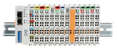 including all the Productivity3000, DirectLOGIC, and Do-more series. Allowing precise I/O count distribution, Protos X supports up to 255 terminals and is scalable from 2 to 4,080 points.
Bus couplers (interface modules) are available in Modbus RTU/ASCII and TCP versions allowing connection of up to 64 terminals per assembly, for a maximum 255 terminals total. Serving as the link between the Protos X I/O and the system’s main controller, the Modbus RTU/ASCII slave bus coupler communicates via a 9-pin D-sub RS-485 port; the TCP server bus coupler communicates to the client via an RJ45 Ethernet port.
Starting at $34, Protos X I/O terminals (I/O modules), are available in two, four, eight and 16-point discrete versions, and two, four, and eight-channel analog versions. There are 12 discrete I/O terminals and 18 analog I/O terminals which include 4-20 mA, 0-10 VDC, and +/-10VDC versions, as well as Pt100 RTDs and Type J and K thermocouples.
Power feed terminals, starting at $18, are available in 24VDC and 120-230 VAC styles to add or change supply power to the terminal power bus; an available 24VDC power distribution terminal with 8 connection points (24V and 0V for each connection) provides access to the integrated 24VDC terminal power bus.
Easy-to-use configuration software (available as a free download) shows the auto-configured Modbus addressing, sets IP (Ethernet) address and communications parameters (serial). Users can also set/disable Watchdog timers, reset bus couplers and more; a communication cable ($56) is available for configuration of the bus couplers. Available bus expansion coupler terminals enable expansion of terminal assemblies with up to 31 expansion couplers in a group, depending on bus coupler chosen.
Protos X components are backed with a one-year warranty. Click here to learn more about the Protos X distributed I/O system.
Protos X I/O FAQs
The Protos X compact, modular field I/O system allows a user to install remote field I/O devices without having to invest in another controller. The unique slim design and low cost of the Protos X I/O makes it the most practical distributed I/O available today.
Here we review some of the features and answer several frequently asked questions about the Protos X field I/O.
Q: What communications protocols are supported by the Protos X I/O platform?
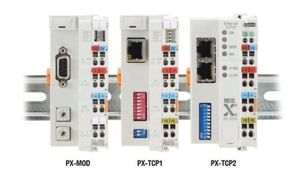
A: Currently we offer three different couplers; all are based on Modbus protocol. At present we offer the serial Modbus RTU/ASCII coupler (PX-MOD) and two different Ethernet Modbus TCP couplers (PX-TCP1 and PX-TCP2). (Figure 1)
Q: What is the difference between the PX-TCP1 and PX-TCP2 Ethernet couplers?
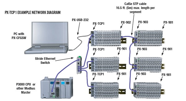
A: PX-TCP1 is a single-port Ethernet Modbus TCP bus coupler that supports up to 64 continuous I/O terminals and is expandable up to a maximum of 255 I/O terminals when used with the PX-902 and PX-903 expansion terminals. (Figure 2)
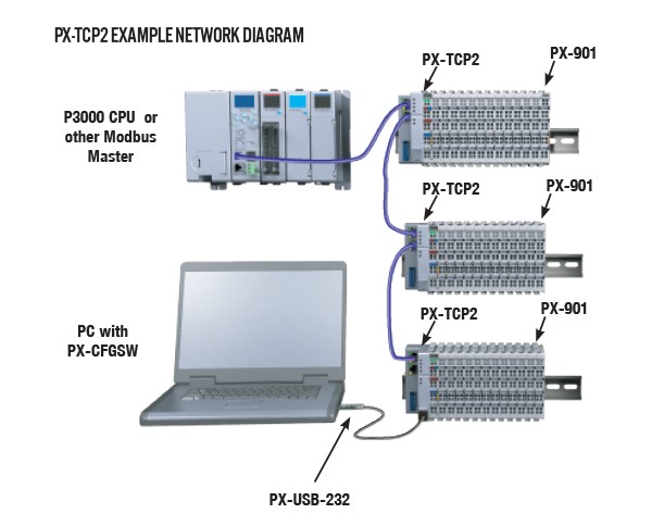
PX-TCP2 is a two-port Ethernet Modbus TCP bus coupler that supports up to 64 continuous I/O terminals. It includes a 2-channel 10/100 Mbps Ethernet switch for connecting to the Modbus TCP Client or to another PX-TCP2. Both couplers support a maximum of 512 input and 512 output bytes. (Figure 3)
Q: Do I need a PX-901 end terminal with every system?
A: You do need an end terminal for each continuous row of I/O terminals. If you are not expanding to an additional row, or if you are using the PX-TCP2, the PX-901 is the correct end terminal. If you plan to expand beyond a single row, each row that is to be expanded should be terminated with the PX-902 bus expansion end terminal, which is used with the PX-903 bus expansion coupler. The final row of a multi-row configuration should end with the PX-901.
Q: How do I know what the Modbus address is for each of my I/O terminals?
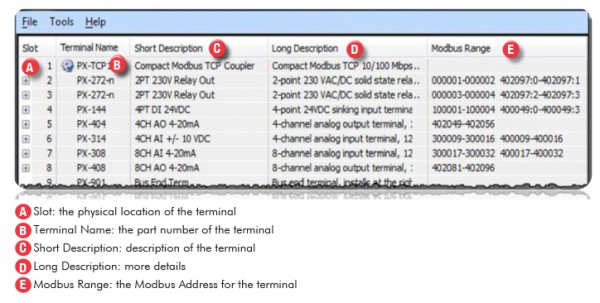
A: It is necessary to connect to your bus coupler with the PX-CFGSW configuration software using the PX-USB-232 programming cable in order to read the connected I/O terminal configuration. The configuration software will give you the Modbus address of each I/O terminal. (Figure 4)
Q: What can be done with the configuration utility?
A: View your assembly’s I/O configuration, including the Modbus addresses of each I/O terminal; view, set and modify the communications parameters; reset the coupler, if necessary; enable/disable watchdog timer and adjust watchdog timeout value.
Q: Are there any restrictions or concerns when assembling my Protos X I/O terminal system?
A: Yes, It is very important to understand the placement of the terminals in an assembly. Always start the assembly with a Bus Coupler and add terminals from left to right, ending with a Bus End Terminal or Bus Expansion End terminal, attaching each terminal as shown in the System Installation.
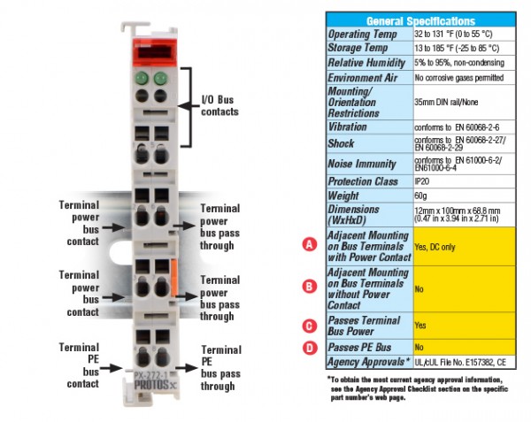
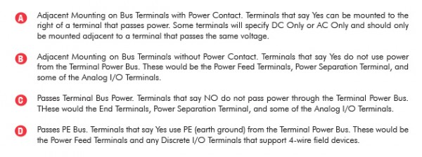
In an assembly there is an I/O Bus, which passes data from the Bus Coupler all the way to the Bus End Terminal via six contacts. There is also a Terminal Power Bus, which can provide power to the terminals and/or field devices via the terminal connections. Power is passed via two or three contacts located on the sides of the terminals. Not all terminals pass the Terminal Power Bus, and the voltages on the bus can vary. Because of this, there are four conditions to take into consideration. These conditions can be found in the General Specifications table for each terminal.
(Figure 5)
 For more articles about programmable control, click here.
Originally Posted: Feb. 2, 2015


