Variable frequency drives are devices for starting, stopping and varying the speed of AC motors to improve control of equipment control and save energy.
A variable frequency drive (VFD) is an electronic device used to vary the frequency of an AC voltage to adjust the speed of an AC motor. VFDs also provide start and stop control, acceleration and deceleration, and overload protection. Many VFDs are networkable, allowing them to integrate into and provide feedback to a process control system.
Most industrial power systems run on alternating current (AC), generally 3-phase but sometimes 1-phase. Therefore, VFDs must be able to vary the frequency of an AC voltage to adjust the speed of an AC motor. To do this, they take advantage of direct current (DC).
This blog post covers why VFDs are used, how they work, the terminology involved, some key features and where they are typically installed.
Many Names for a VFD
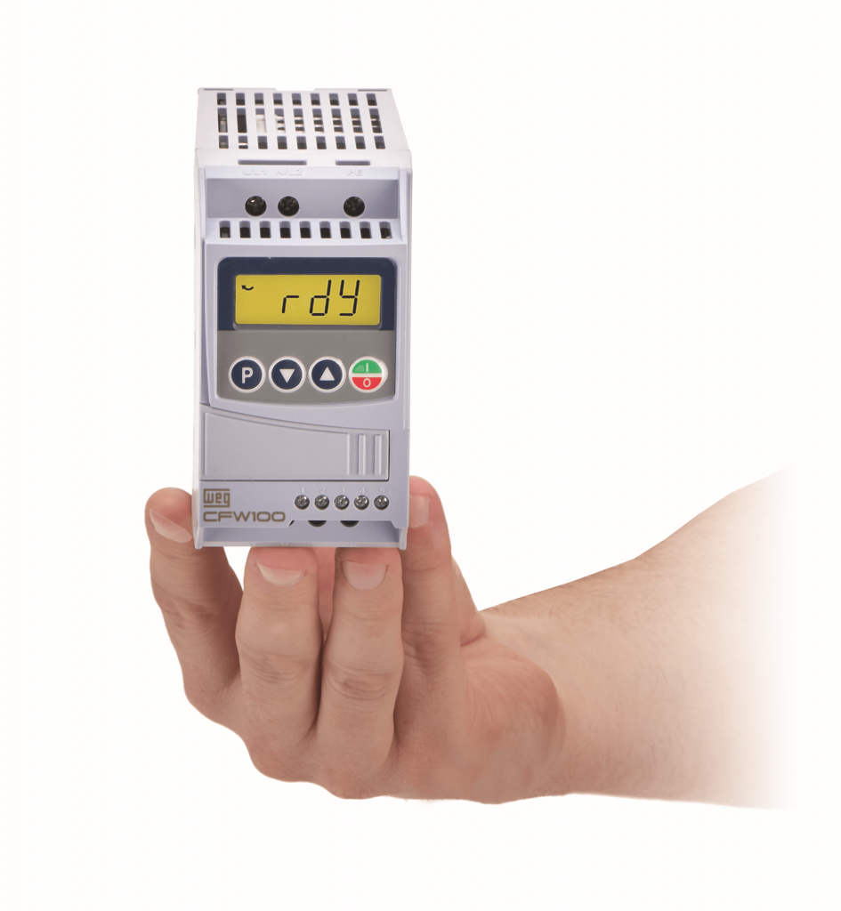
Suppliers and designers may use many names or abbreviations for VFDs, even though the basic functionality and form factor is the same (Figure 1). Here are some common names and abbreviations:
- AC drive
- Adjustable frequency drive (AFD)
- Variable speed drive (VSD)
- Adjustable speed drive (ASD)
- AC inverter
How a VFD Works
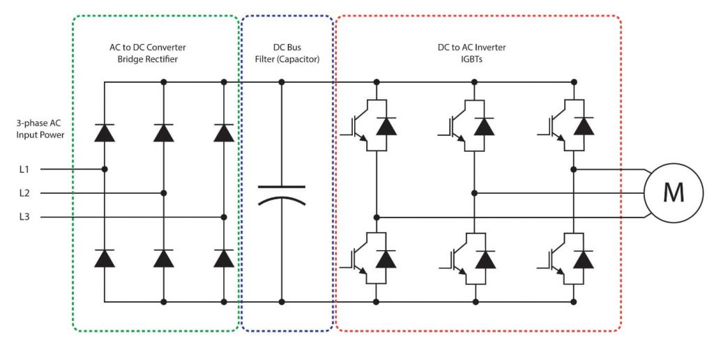
The way a VFD converts AC input power to a variable output can generally be described by looking at the following three features (Figure 2):
- AC to DC Converter
AC input voltage is passed through a diode bridge which produces a rectified DC voltage on the DC bus. - DC Bus
As an example, with a typical 480 VAC 3-phase input voltage, the DC bus will hold a charge of about 650 VDC, with actual bus voltage depending on the line voltage level and motor load. The reason the DC bus voltage is higher than the nominal input line voltage is due to the root-mean-squared measurements of AC sine waves (the “peaks” of a 480 VAC sine wave are about 679 volts, which isminus the ripple). An electrolytic capacitor is added to the DC bus to filter undesired AC frequencies and hold the charge.
- DC to AC Inverter
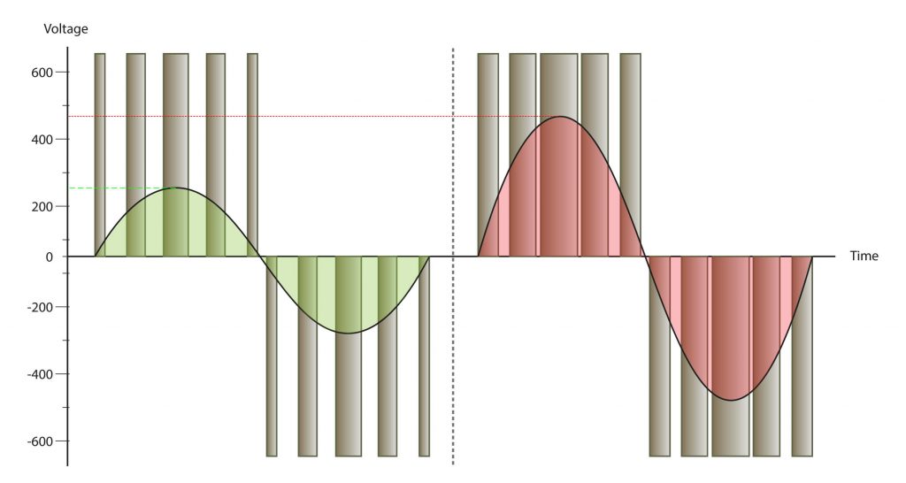
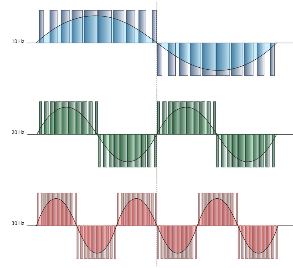
The DC voltage is then synthesized back into 3-phase AC output voltage through a series of switches or transistors. The most common ones in use today are insulated gate bipolar transistors (IGBT). These fast switching IGBTs are operated rapidly to create a square wave using pulse width modulation (PWM). PWM square waves create an AC signal based on their frequency (the number of on/off cycles per second) and duty cycle (the width or duration of how long the signal remains on during each pulse) and the amplitude (the height of the pulse determined by the DC voltage level), as illustrated in Figures 3 and 4.
VFD Control Modes
A VFD may use different control modes (or algorithms) to modulate the voltage, and some modes are better than others for various applications. These may vary between different VFDs and manufacturers, but here are some common modes and a comparison table (Figure 5):
- Volts/Hertz (V/Hz or V/f)
This is the simplistic and most common control method seen. It requires fewer parameters to be set, and in many cases can operate basic applications from the default settings. Various settings are available within the V/Hz mode such as:- High starting torque
- Fan and pump mode
- 1.5 power curve
- Square curve
V/Hz mode may accept an encoder feedback from the driven motor, allowing the VFD to make additional calculations and provide more precise speed control. Starting torque for V/Hz control is typically 150% @ 3 Hz.
- Vector Control
This mode yields a much higher-performance control using known or measured motor characteristics like efficiency, slip and power factor. These and other parameters are used in the calculations to provide greater torque at lower speeds and more accurate control. There are many applications where torque control is more important than speed control, and vector control is needed in these situations. Starting torque for closed-loop vector control is typically 200% @ 0 RPM. This type of control is needed in applications where the motor needs to hold a load, like cranes and elevators.
| Volts/Herts | Vector | |
| Feedback | Not required | Requires encoder |
| Auto-tuning | Not required | Required (for optimal performance) |
| Starting Torque | 150% @ 3 Hz | 200% @ 0.3 Hz (@ 0 RPM for closed loop) |
| Configuration | Simple setup | More complex |
| Performance | ± 2-3% of max. speed | ± 0.03% of max. speed |
| Max Frequency | 400 Hz | 600 Hz |
Benefits of Using VFDs
Using VFDs to control motor speed not only provides safe, precise and adjustable regulation, but can also deliver energy efficiency savings. Here are some specific benefits that end users may need or desire:
- Speed Control
Motor speeds can be varied for optimizing automated process applications like conveying, fans, pumping and machining. - Controlled Start/Stop
VFDs offer more intelligent options for starting and stopping motors such as acceleration and deceleration parameters for ramping motor speed up and down in a more controlled manner, reducing wear and tear on the motor and the driven load. - Reduced Energy Consumption
To save energy, motors can be run slower at just the speed needed by the driven load. Another consideration is that many end user electricity costs are calculated based on peak usage. AC motors started with a traditional across the line motor starter may experience a current inrush as high as 20 times the normal full load, which can be minimized with a VFD, resulting in substantial savings. - Improved Safety
VFDs with safe torque off (STO) are becoming common in newer models, providing the most basic integrated safety circuit for a drive. STO ensures the VFD cannot generate any torque to the motor and prevents starting if an unsafe condition exists. - Advanced Features
Some VFDs include logic features and additional input/output control signal capabilities on-board to enable increased safety and performance. Speed profiles and multiple speed steps can be optimized for equipment and products.
When selecting a VFD, users should examine the full feature set and consider at least the basics presented in this article so they can choose a VFD to safely meet the performance requirements of their application at a reasonable price point.