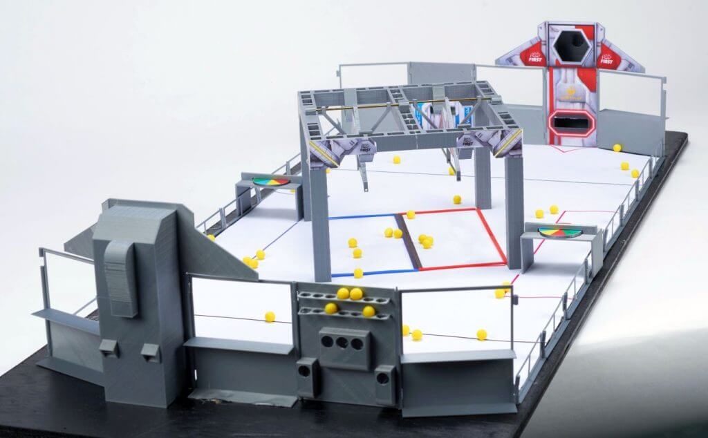
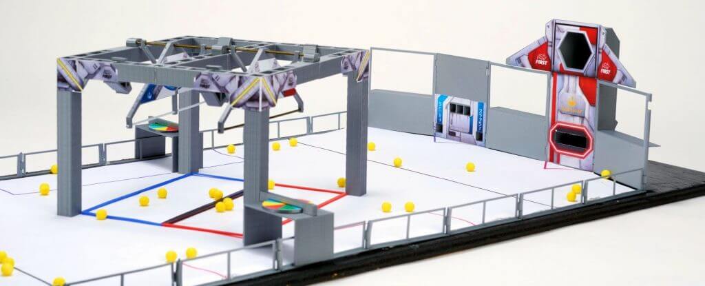
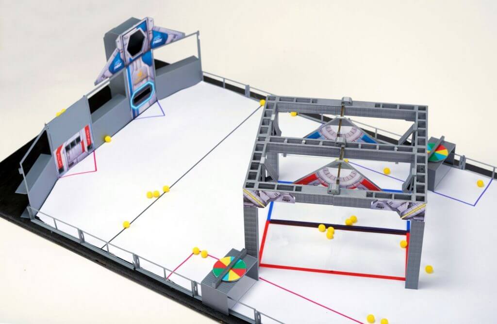
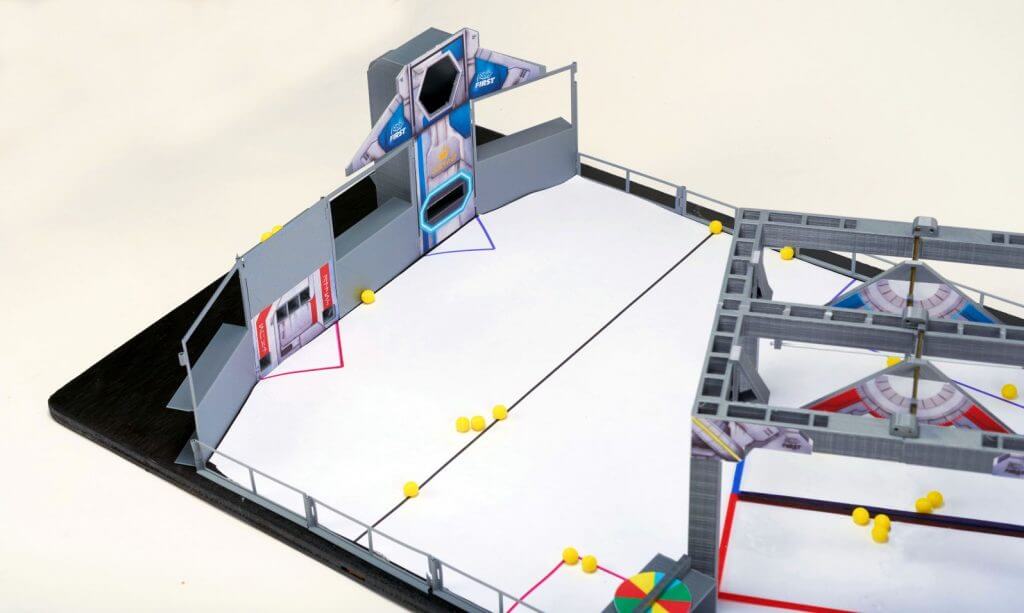
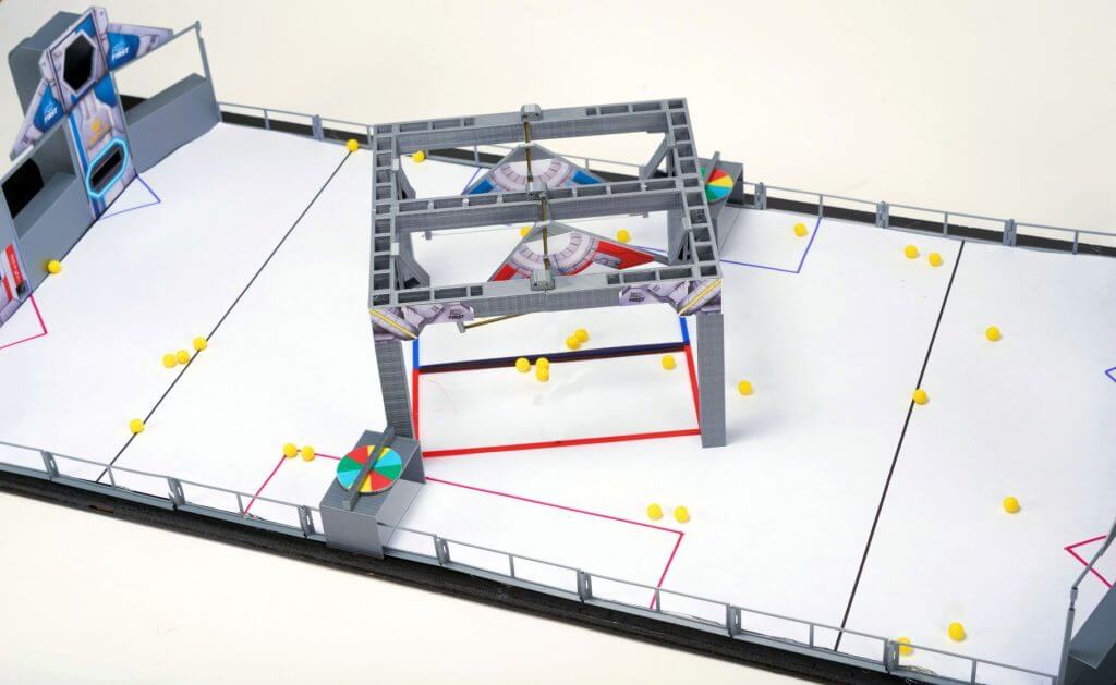
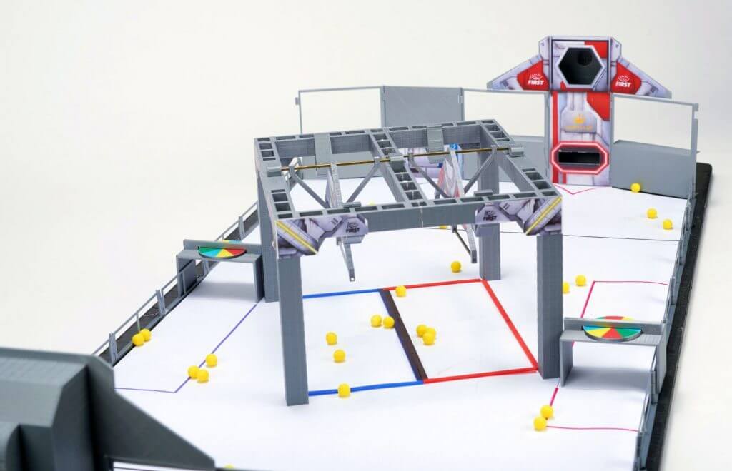
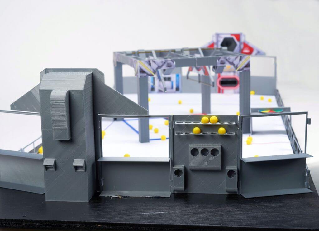
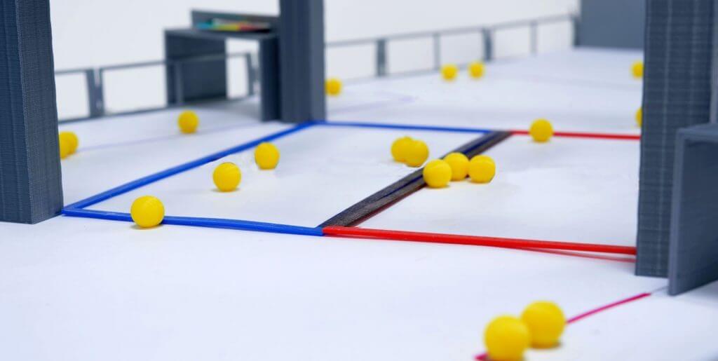
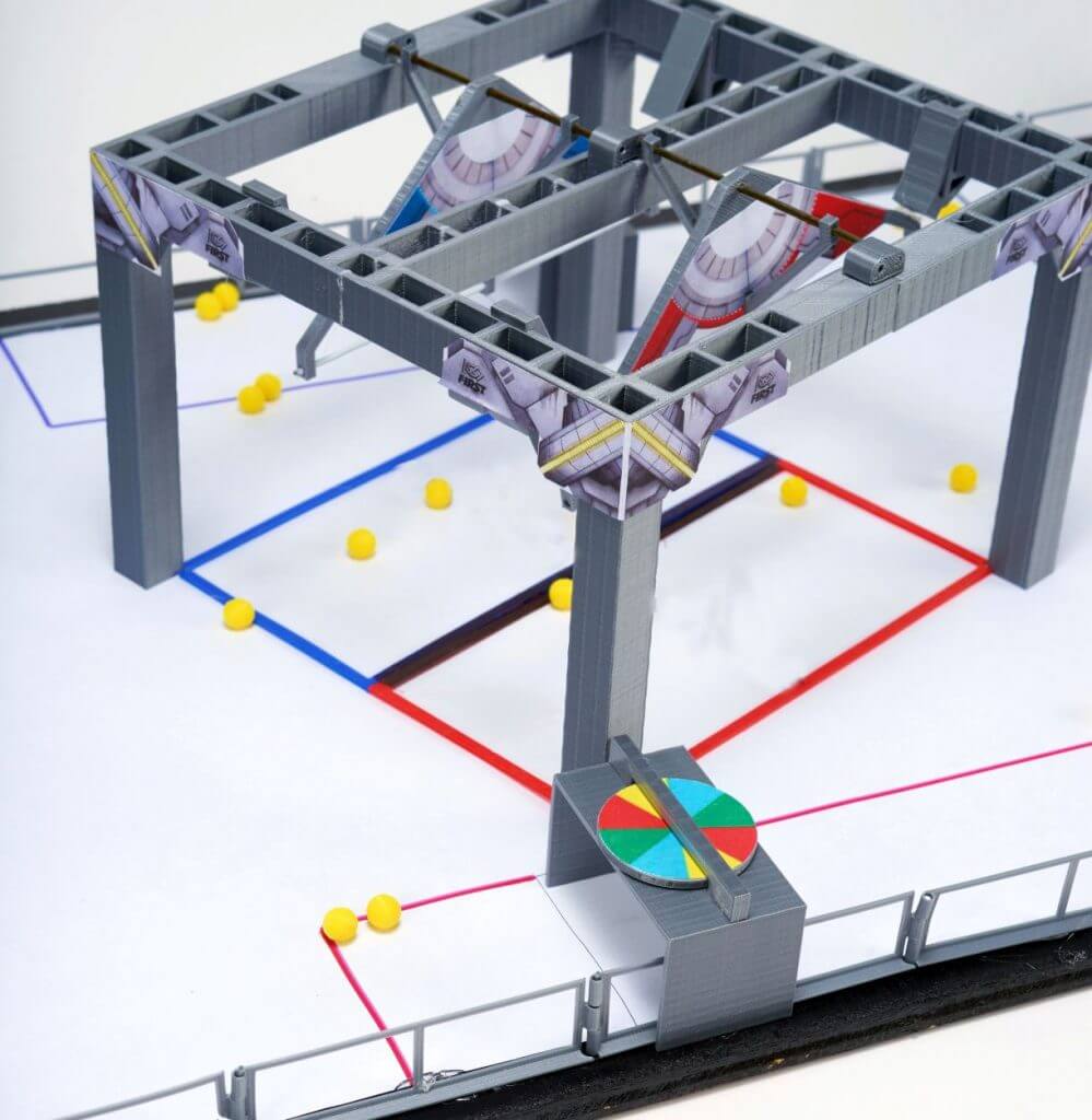
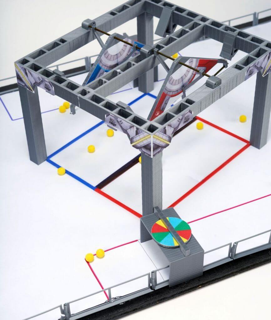
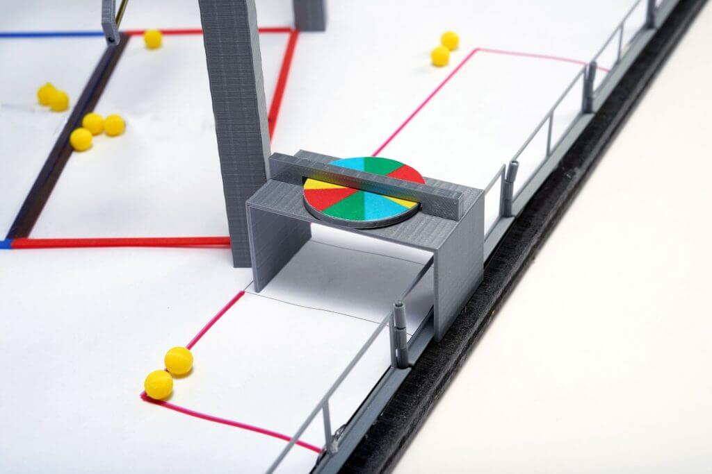
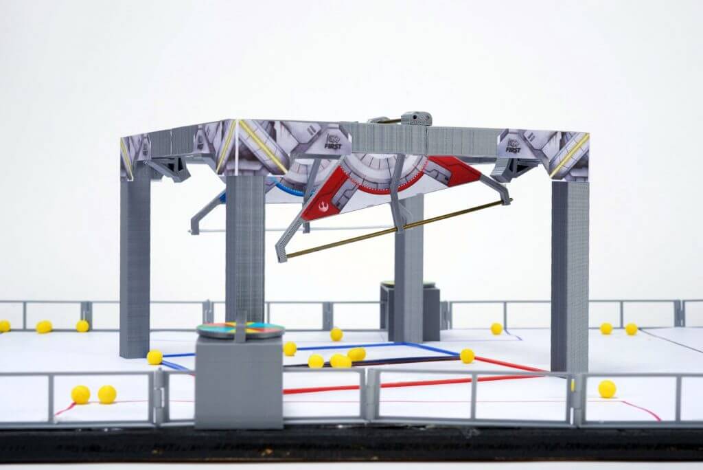
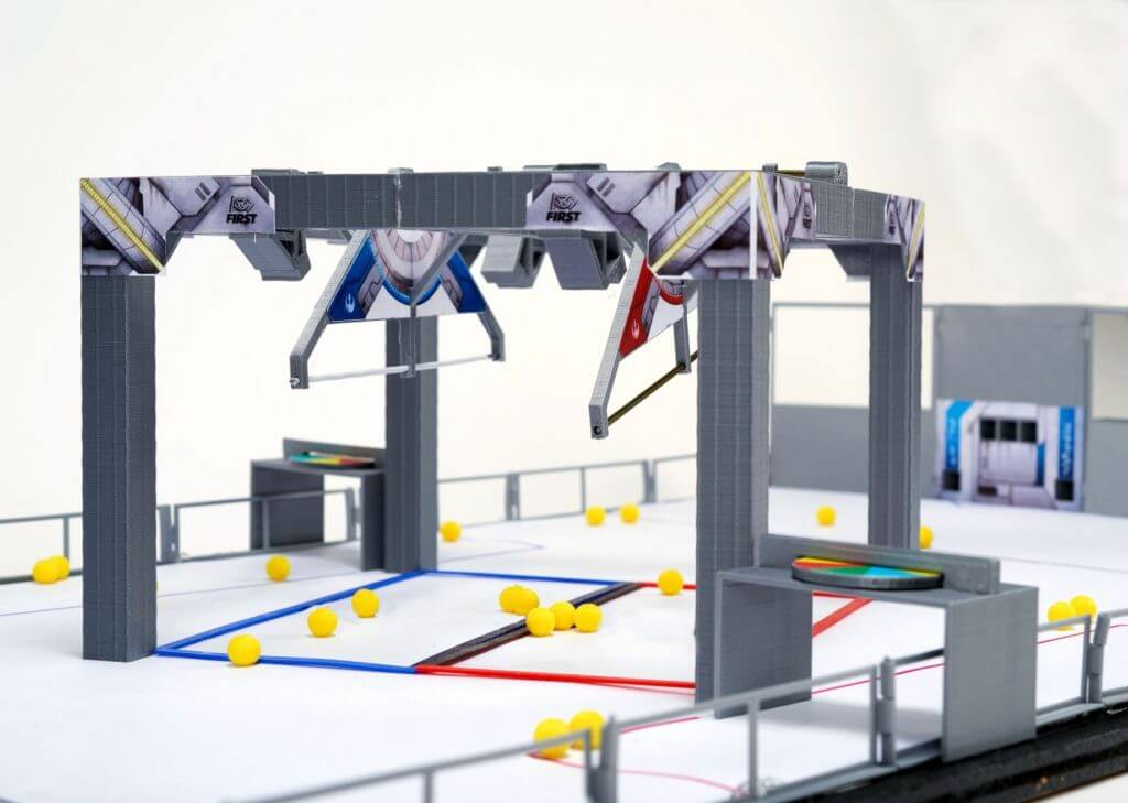
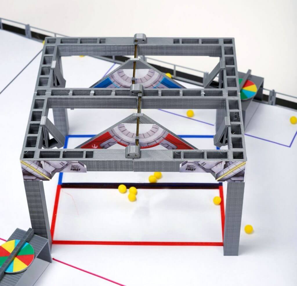
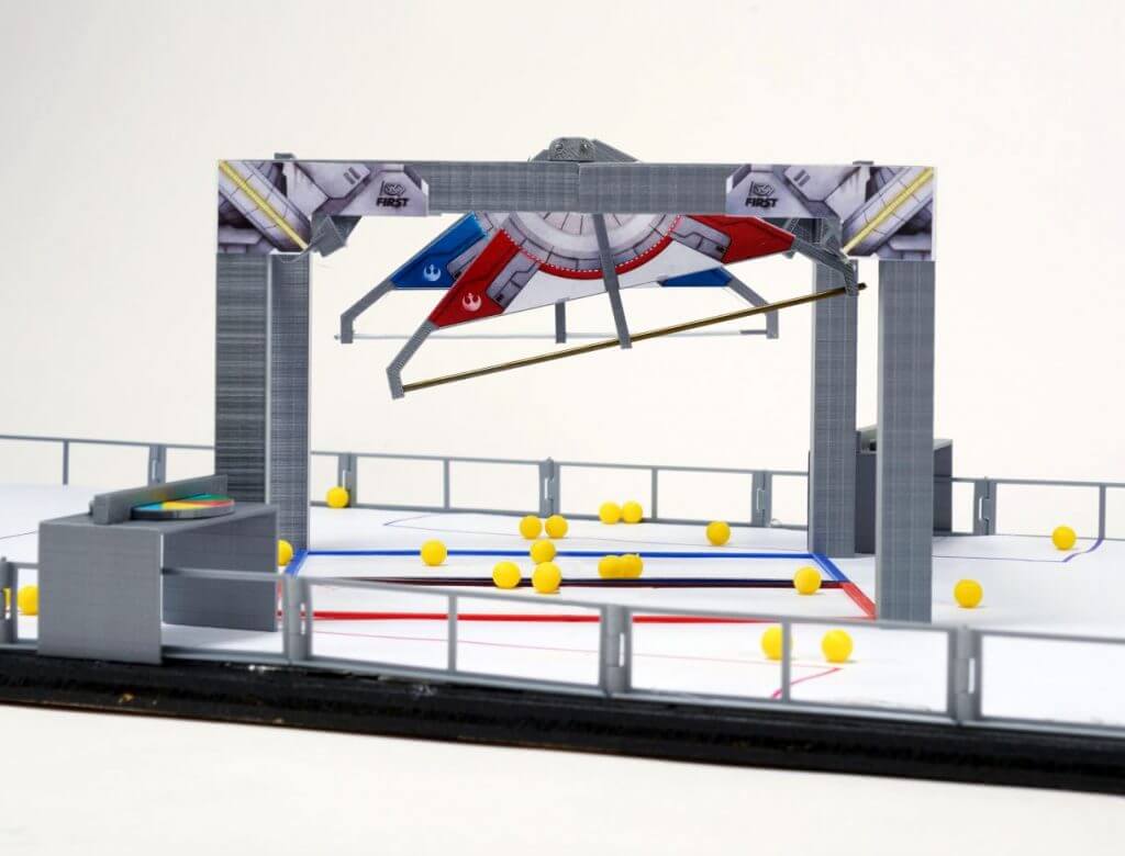
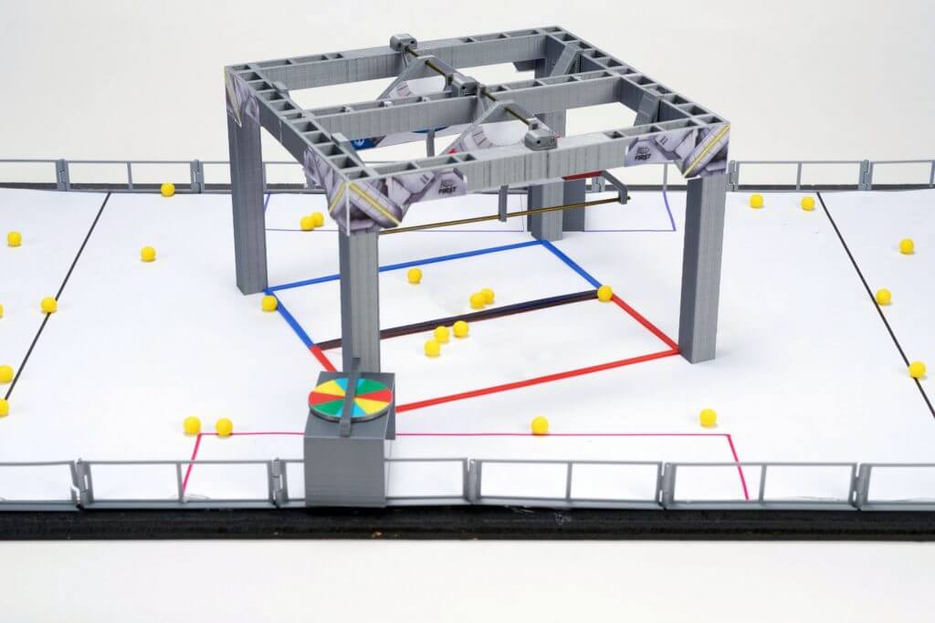
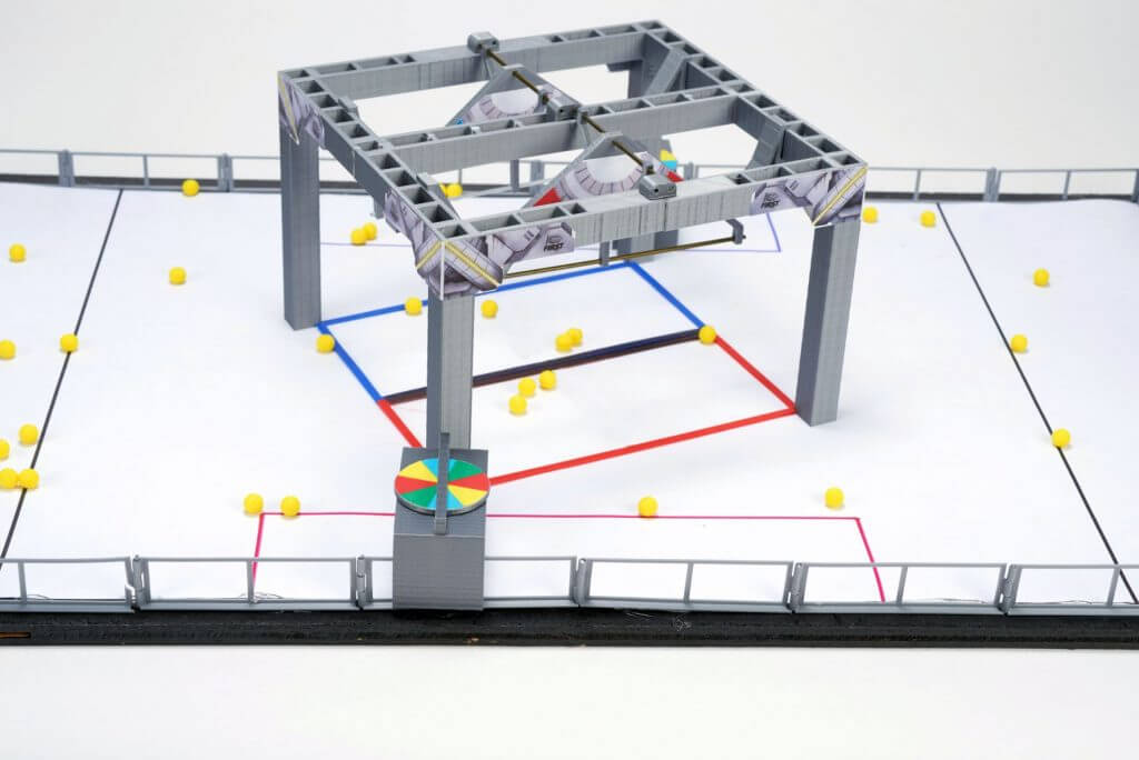
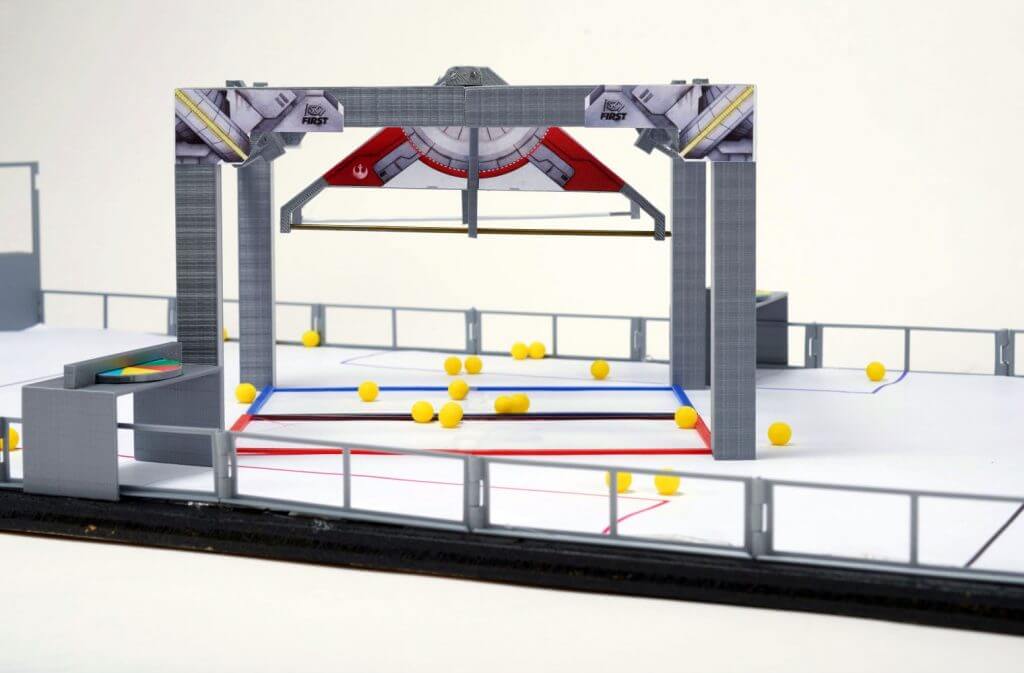
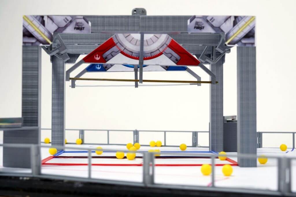
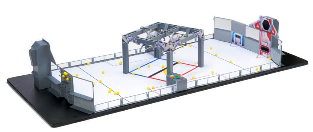
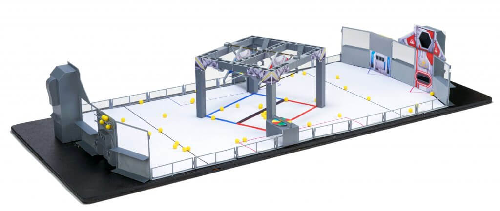
20:1 Scale Model of the 2021 Field

AutomationDirect’s animation team converted the animation models into 3D printable models for you to play with. This is the “playing field” for the FIRST Robotics Competition game for 2021. For more info about FIRST and the 2021 game: “INFINITE RECHARGE” – please visit the FIRST website.
>>>> CLICK HERE to download the STL Files, Graphics, Floor Mat
(These are identical to the 2021 models, except the “GeneratorBerm2021.STL” file)
These models are NOT intended to be accurate representations of the actual field – please do not use them for ANY game, rule or ‘build’ decisions. These models have been highly modified from the actual field drawings to make them easy to 3D print and assemble and to give the general appearance of the actual INFINITE RECHARGE field. To paraphrase from the Latin – Caveat Printor! – Let the printer beware!
All parts should fit together, but that depends heavily on your printer accuracy. Hopefully, they are close enough that you can file things down a little if needed. The examples shown here were all printed on an inexpensive, low-end RepRap 3D Printer – so any printer you have should be able to print at least as well.
NOTE: We are NOT CAD experts, so if you see ways to improve these PLEASE do so and send us a copy – we will add it to the library. Let’s make this a community project!
Print settings we used for all items:
- 0.2mm layers
- Shell .4mm
- Top and bottom .4mm
- Fill 20% – you may want to print some of the thinner parts at 100% fill
- PLA: extruder 190, bed 60
- No supports (except the Goal which uses base support only)
While we have your attention
Have you used your AutomationDirect $35 Kit-Of-Parts Voucher yet? You know – for the real-world robot! If not, have your lead mentor log on to the FIRSTinspires dashboard to get your team’s voucher code – THEN follow these simple (BUT IMPORTANT) instructions to activate and use your voucher. We’ve got thousands of parts that can be used to help build your ‘bot. Check that link for a list of products that are popular with FIRST teams.
Assembly Instructions:
Apply Graphics
Print graphics from included file and apply to field elements. We like to use “Re-positionable Adhesive” because it allows you to remove and re-position the graphics. Krylon, Elmers and 3M all have versions of this.
Field Perimeter Assembly
Print the following items:
Qty Item
6 Driver Stations – print face down
2 Power Ports – print face down with supports touching printer plate
2 Loading Bays – print face down, should not need supports
16 Side Rails – face down
Step 1: Remove 3D Printer Supports from Power Ports:
To remove the supporting material, just cram some needle nose pliers in and twist and pull. Repeat that a couple times to quickly tear out all the supports for the mid goal:


Step 2: Apply graphic decals to Loading Bays and Power Ports:

Hint: Cut the ball boles AFTER applying the graphics
Step 3: Assemble Two Driver Station walls face down using 1.75mm filament as pins

Step 4: Add guardrails
Assemble 8 guard rails by inserting enough filament to span the hinges (don’t need to go all the way up the wall). Trim excess filament off. No need to glue it in place.
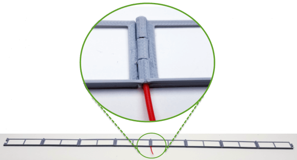
Use 8 guardrails per side
Insert final pins between portals and side rails:

Use a straight edge to align side rails and tape or glue side rails to surface (angle aluminum works well for aligning the rails and hot glue works well for securing it to the surface):

Shield Generator Assembly
Print the following items:
Qty Item
2 Shield Generator Quarter Part A- print upside down
2 Shield Generator Quarter Part B – print upside down
2 Generator Switches
2 Generator Switch Outer Supports
2 Generator Switch Center Support
Sand edges to be glued, apply a dab of super glue on all mating surfaces and clamp the 4 sections as shown:


3D Print Switch bumpers and supports:

Print Generator Switch Parts:

Apply Decals (note the added cutout …):

Assemble the Generator Switches (Decals not shown for clarity)

Add the Generator Switch supports, bumpers, and corner decals. We used super glue though hot glue would work fine too.
HINT: Use the switches to align switch supports as shown in second image:

This model is designed to use standard coat hanger wire to support the Generator switches, though you can use anything you want.

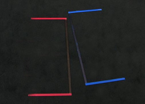
3D Print Red and Blue Boundaries and use a black marker to modify the color as shown:
CONTROL PANEL ASSEMBLY
Print the following items:
Qty Item
2 Trench Control Panel
2 Trench Tunnel Sensor Bar 2 Trench Tunnel Color Wheel 2 Control Panel Rocket Decals
Use a drill bit to enlarge hole in tunnel so wheel spins freely:

Assemble as shown:

POWER CELLS
Print the following items:
Qty Item
96 Power Cell Half
Assemble as shown:

Assemble Field
Print the following items:
Qty Item
1 Floor Mat (Carpet)
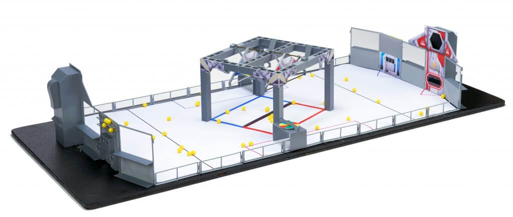
Hint: The field came out a little narrow so the generator and control panels don’t really fit as intended. The simple fix is to place one leg of the Control Panel OUTSIDE the guard rail.

Please let us know what you think and if you can show us a better way to do this!
3D Modeling Contest
Keep an eye out for the 2021 3D-modeling contest where you submit a 20:1 scale model of YOUR robot to fit on this field!
You can reach us by e-mail:
educationalcontacts@automationdirect.com
Or on Chief Delphi:
Rick Folea: user: rfolea
Chip McDaniel user: only1chip
Additional Photos:
To read more articles from AutomationDirect, click here.


