The Midwest Propulsion Group is a jet engine club dedicated to increasing the engineering knowledge and experience base of students by providing real-world engineering tasks related to gas turbine restoration and performance analysis, as well as finding vehicular applications for such engines.
Comprised of students and professional engineers from the Cincinnati/Dayton area and engineering co-ops from varying universities, the group meets weekly to increase hands-on knowledge of younger engineers while having fun and also promoting engineering at local high-schools and aerospace venues.
The team is currently using DirectLOGIC programmable logic controllers (PLCs) to automate the starting sequence of gas turbine engines, as well as monitor performance to ensure the engines are operating within established parameters. If the engines operate outside the desired envelope, the PLCs terminate the operation automatically and display the appropriate programmed fault.
Part I: The Solar T62T-32A Hydro mechanical Engine
The Solar T62T-32A gas turbine engine was originally installed in a military generator set which included appropriate controls to start up and run the engine to provide desired electrical power.
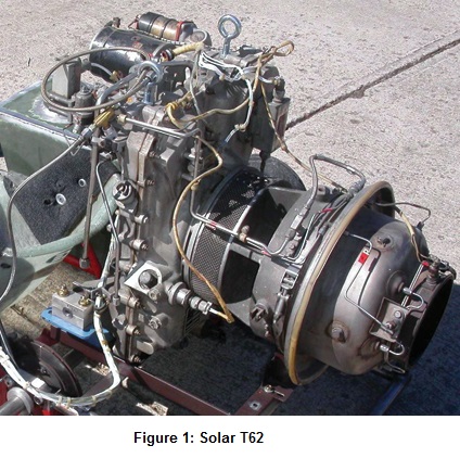
The gas turbine runs at approximately 60,000 RPM and was geared down through a planetary gearbox to 6,000 RPM, which then drove a 3-phase, 60kW AC generator. The controls needed to be redesigned since the original controls were not available and the intended application changed. A view of the gas turbine removed from the generator is shown in Figure 1.
Thee engine start-up operational sequence follows:
1) When the system is powered up, the transfer pump is turned on.
2) Once the “start” command is initiated, the electric starter and igniter turn on simultaneously.
3) At 4% engine speed, a single fuel nozzle is opened (torch nozzle) and combustion begins.
4) When the engine accelerates to 10% speed, the fuel manifold is opened with six fuel nozzles (main fuel).
5) Once the engine reaches 78% speed, the starter and igniter disengage; the engine speed keeps accelerating on its own power.
6) At 96% speed, the torch nozzle is disengaged and the engine continues running at 100%, which corresponds to a frequency of 2,000 Hz on the magnetic pick-up.
The original generator configuration monitored the oil pressure, exhaust gas temperature (EGT), and speed. If any of the parameters exceeded established limits, such as a loss of oil pressure or the engine got too hot, the engine would shut down.
 The engine has hydro-mechanical controls, which means that the fuel scheduling is based on mechanical inputs. The fuel control/pump is gear-driven and fuel is scheduled based on engine speed and compressor pressure. In addition, to maintain constant engine speed as a function of varying load, a governor watches engine speed (frequency) and outputs voltage to the torque control motor (i.e. throttle) which is also connected to the fuel controller.
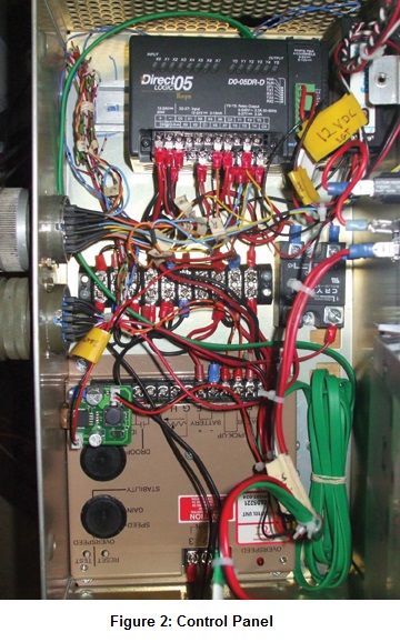
The team modified the engine controls by using a DirectLOGIC D0-05DR-D PLC with an F0-04AD-2 analog input module and a six-inch C-more (model EA7-T6C) touchscreen HMI display. The PLC controls the start sequence by engaging and disengaging accessories as a function of engine speed, while the input module monitors how well the engine starts and continues running; different parameters are used for each.
To keep the engine running at 2,000 Hz (100% speed), a commercial diesel engine governor is used to schedule the fuel to the engine via a fuel torque control motor.
The PLC’s analog input card requires signals in the 0-10V range. Appropriate signal conditioning was used to convert engine speed and thermocouple readings into the appropriate voltage ranges. The team initially faced some challenges getting accurate speed readings at all engine speeds (which determines when the PLC actuates accessories) because the signal pulse changed shape and amplitude. This was easily solved with a single resistor.
A view of the control panel with the DL05 PLC, signal conditioning modules, and fuel governor can be seen in Figure 2.
Programming Flowchart
Using a C-more touchscreen, the operator enters a menu screen and then chooses one of the following options:
1) Run the engine
2) Test the outputs – actuate each output independently to verify functionality
3) Administrator screen adjusts fault setting for both start-up and steady-state running
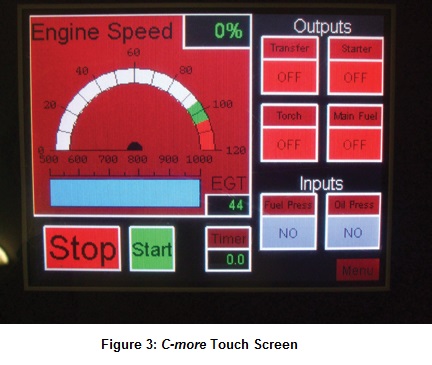
A view of the engine “start-up” screen showing the temperature, speed, and inputs/outputs from the PLC is shown in Figure 3.
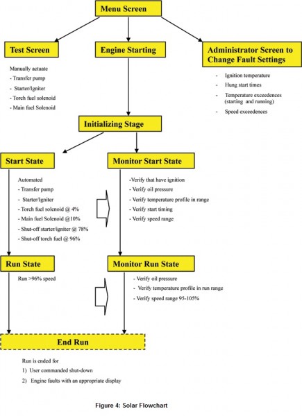
Once the engine “start” button is selected, two major states run in parallel in the ladder logic: the starting/running state and the monitoring state, which make sure the parameters of interest are within the appropriate limits. The program switches from starting mode to running mode when the engine reaches 96% speed, at which point the “torch” nozzle is also disengaged. A simplified programming flowchart is shown in Figure 4.
Faults
By automating the engine sequence with the PLC, not only can it be started more smoothly/reliably, but it is also safer and easier to troubleshoot when the engine does not perform as desired. Some of the faults detected with the program include:
1) Failure to light ensures fuel ignition occurs by checking if a set temperature is reached within a prescribed time from the starting.
2) Temperature limits The engine has to stay within pre defined temperature ranges for both starting and steady-state running.
3) Hung start The engine has to reach 100% (and intermediate speeds) within a desired time and is not allowed to slow down or reverse speed during starting.
4) Loss of oil pressure Oil pressure has to be maintained at a given pressure to continue operation.
5) Speed limits The engine has to stay within 95-105% while running in steady state.
Application
With the engine fully automated, it can be used in an automotive application, and use the shaft power coming from the planetary gearbox at 6,000 RPM.
The plan is to run the engine at constant speed and use a continuously variable transmission (CVT) to transfer power to the wheels. The CVT primary would be adjusted, possibly hydraulically, by the car foot pedal (throttle) to vary output power.
Part II: Tiernay TT-10 FADEC Engine
The team is also automating a second gas turbine, a Tiernay TT10. Like the Solar T62T-32A, this turbine was also taken from a military auxiliary power unit (APU).
The engine runs at 50,300 RPM and, through a planetary gearbox, reduces to a 12,000 RPM shaft output speed used to run a DC generator which yields 28V DC (10kW) for starting and running aircraft on the ground.
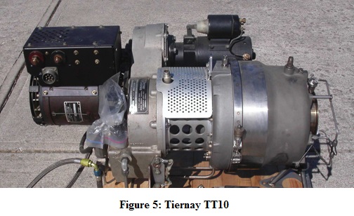
A view of this gas turbine in our intended application (a shifter kart) is shown in Figure 5.
This gas turbine is different from the Solar in that it is run by a Full Authority Digital Electronic Controller (FADEC), which means the engine follows a computer program to run a high-pressure fuel pump to achieve the desired speeds.
The FADEC sends 24V pulses to the pump of varying duration (pulse-width modulation, PWM) to accelerate or decelerate the engine. There are no mechanical inputs to the controller. The only inputs are engine speed (variable), engine temperature (variable), and oil pressure (discrete).
From data logging the engine supplies and from the limited documentation, it was found that the controller would start the engine with a constant output PWM to the fuel pump. Once 50% speed is achieved, the output transitions to a PID loop where PWM output is varied as required. A screen shot of four of the parameters recorded during data logging is shown in Figure 6. 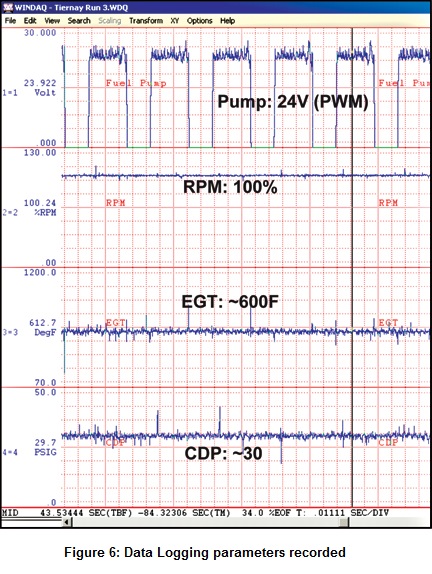
For this engine, the team chose the DirectLOGIC DL06 (model D0-06DR-D) PLC with the F0-04AD-2 analog input module and the 8-inch C-more (model EA7-T8C) touchscreen HMI to run the engine at start-up with a pre-defined, fixed output. Once the engine reaches 50% speed, the PLC switches control to a commercial digital engine governor to vary the output to the high-pressure pump and keep it at desired speed.
The PLC actuates all the accessories in sequence, and also switches from the starting PWM circuit to governor control.
In addition, the larger D06 PLC with more relays and card slots was selected to allow for future automation. For example, the intended application requires use of the gas turbine electrical generator to make a turbine-electric go-kart. To vary the throttle electrical output, a control circuit will have to be made that will also be actuated/automated by the PLC.
Status: At press time, the team was in the process of finishing bench tests, finalizing programming of the touch screen in the test stand, and was preparing to start test runs of the gas turbine itself. Once the engine runs reliably, the focus will shift to varying the generator output based on user demand.
Also, the team now plans to use the Solar T62T-32A gas turbine engine to power a hovercraft, instead of in the original automotive application.
To learn more about the various club projects, feel free to contact William Rossey at: therosseys@cinci.rr.com.
By William Rossey
Midwest Propulsion Group
Disclaimer: AutomationDirect does not guarantee the products described in this article are suitable for your particular application, nor do we assume any responsibility for your product/system design, installation, or operation.
Originally Posted: Dec. 12, 2012


