Programmable logic controllers (PLCs) are available in a variety of sizes for applications big and small. While the application’s hardware requirements often drive the PLC selection, the programming software’s capabilities should also be considered as it has a significant effect on program development.
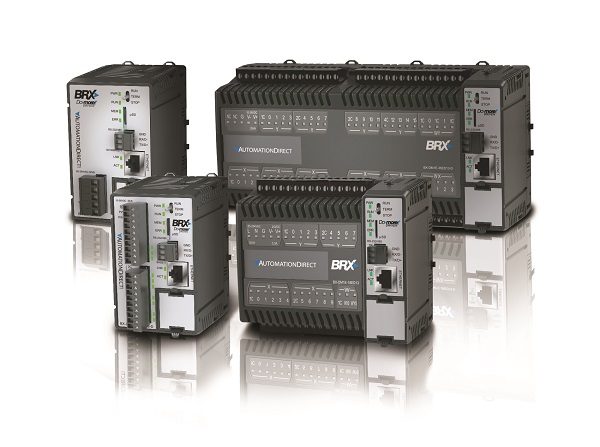
Some programmers may open the PLC programming software, create a new project and start creating ladder logic immediately—but this can lead to configuration-on-the-fly, not the most efficient technique. Instead, depending on the controller selected, the programming software may have built-in features allowing configuration based on menu-driven selections, which is often the better path (Figure 1).

In his July 2017 Control Engineering “Controller Embeds Programming Efficiency” article, Bill Dehner explains how top-down configuration and device-centric methods help lead a programmer down a quick and productive path. Bill Dehner, a Technical Marketing Engineer at AutomationDirect, explains how built-in, menu-driven choices configure devices, which then handle common functions behind the scenes with little programming required.
An example of this efficient programming can be found in AutomationDirect’s Do-more Designer PLC programming and documentation software, available via CD or free download. This article discusses top-down configuration and device-centric programming, possible with software such as Do-more Designer. The article also includes examples of how these concepts can be used to improve programming efficiency in Do-more controllers like the BRX micro PLC.
What is Top-Down Configuration?
In the Control Engineering article, Bill Dehner explains top-down configuration. “For some controllers, configuration is simplified using a top-down method (Table),” he says. “The order of the tasks listed in the Table is by precedence, with each item in the list depending on the item or items above it. For example, everything below CPU configuration depends on how the CPU is configured. Serial port, port type, Ethernet I/O Master options and server options such as Modbus/TCP and EtherNet/IP Explicit messaging are all configuration selections typically available during CPU configuration. These selections add necessary parameters to some or all the items below CPU configuration.”
Table: Step to Top-Down Configuration
- CPU Configuration
- I/O configuration
- Module configuration
- Device configuration
- I/O mappings
- Memory configuration
Setting up a controller in the proper order can simplify a software development project by automating certain steps, and by helping below tasks fall into place. For example, when configuring an EtherNet/IP Server, only the appropriate parameters are exposed in subsequent configuration dashboards.
Device-Centric Concepts
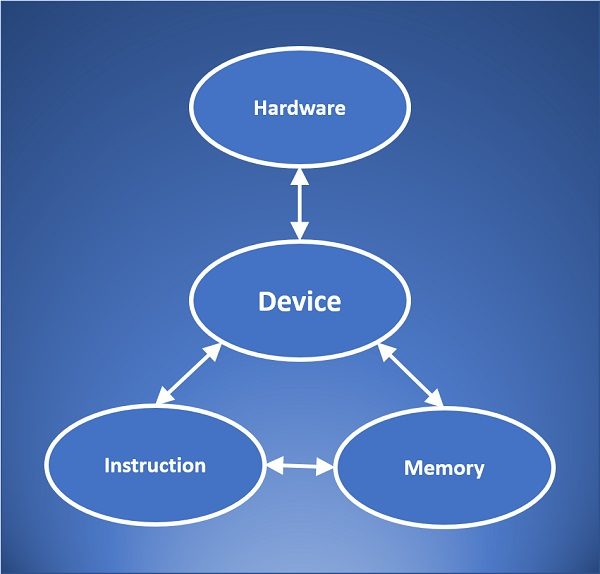
Following a methodical top-down configuration leads to device-centric concepts. With device-centric, the device is in the middle, so the ladder diagram program talks to the device, not directly to the hardware (Figure 2). These device drivers take care of low-level details, freeing the programmer to concentrate on the application.

“What is a device,” asks Dehner in the article? “A programmer likely thinks of a device as a sensor, encoder, I/O module, variable frequency drive (VFD), EtherNet/IP module, remote rack, or a similar piece of hardware,” he says. “In a device-centric controller, the devices are instead pieces of code between the program and the hardware. Using this concept, the device is configured, and it handles the details for control of the hardware by the controller such as establishing communication protocols, handshaking and defining memory requirements. Much of the hardware details are handled via configuration of each device, not with controller programming.”
A program instruction talks to a configured device, not to the hardware directly. Configuring a device defines memory and creates related variables, handshaking bits and memory flags.
A comm port device sends data to and from memory. As data is transmitted and received, buffering and status flags in memory are handled by the device. With device-centric programming, everything passes through the device which handles the details, behind the scenes.
A server is a device as well. Again, it talks directly with hardware. It runs in the background managing the data moving between memory and the hardware. An example is a Modbus/TCP device. It is configured, then functions mostly outside of the program, but the program accesses it to send and receive data.
Using Devices Efficiently
“Regardless of the complexity of the hardware selected, the device provides a clean, uniform interface between the hardware and controller program,” says Dehner in the Control Engineering article. “Each device is set up the same way, for example a Modbus/RTU or a general-purpose serial port, by following top-down configuration steps which require selecting features and filling in a few blanks.”
A typical application was discussed in the article—a box diverter. It contains a variety of hardware that is often controlled by a PLC. This includes encoders synchronizing a conveyor to a diverter gate dependent on box length, a VFD controlling a motor, and barcode scanning of a box on the conveyor to divert it to the proper destination. There are also inputs and outputs used to connect sensors and pneumatic actuators to detect a box and control a lift.
“As this box diverter application demonstrates, it’s not unusual to have several different pieces of automation hardware connected to a PLC, with each hardware component and its required connections defining the devices,” says Dehner in the article. “However, in this instance, a controller utilizing top-down configuration and device-centric concepts is quickly configured, with much of this effort performed automatically.”
“If the controller lacks on-board high-speed inputs, a high-speed counter module can be used to count the quadrature pulses from the encoder”, continues Dehner. “This module is not a part of the CPU configuration, but it is automatically discovered in the second step, I/O configuration” he says. “The third step, module configuration, will then autofill the needed parameters with default values for the discovered module. Any edits to the configuration required can be made here during this step. The PLC will automatically handle the I/O mapping for the added module, and create the needed image register addresses.”
Configuration and use of the built-in Ethernet port “device” in a controller such as the BRX begins at the top of the configuration list. During the CPU configuration step, the Ethernet I/O master is selected to enable it. When enabled, IP configuration and other communication options are created in the I/O configuration. At this point, the device is available for use in the program, since the I/O mapping is completed automatically.
In the article Dehner also discusses how the controller’s serial port uses simple ASCII text strings to communicate with the barcode scanner. “The port is recognized during the CPU configuration step, where a general-purpose serial port is configured including settings such as baud rate, and hardware protocols such as RS-232,” he says. “I/O and module configuration is not needed, and the device configuration is created automatically, providing a pre-configured interface with access to system resources. The memory configuration step automatically allocates memory for the device.”
In this diverter example, multi-point discrete input and output modules are used, which is typical in many automation applications. Similar methods are used to configure these modules. While some devices are more complicated to set up than others, they all use the same configuration methodology. Each is configured starting at the top of the Table, and then working down. By following this methodology, only parameters that need to be configured are accessible, and much of the configuration is automatically defined.
Effective Instructions
The diverter example above shows how a top-down and device-centric controller programming speeds configuration. The BRX controller using Do-more Designer programming software offers efficient PID loop and motion control instructions as well.
Many different control loops require the use of PID instructions, and Do-more Designer provides additional PID instruction features and functionality including run-time configuration, modularity and interchangeability.
“Part of this improved efficiency is the result of breaking down the PID loop into smaller pieces,” says Dehner in the article. “Instead of embedding all the PID parameters such as filters, scaling, ramp-soak tables and alarm handlers in one PID instruction, separate instructions are used to access the parameters individually to simplify customization of these control algorithms. These instructions can also include trend views for display to help with understanding of the control loop response, and to assist with initial tuning and troubleshooting.”
Motion control instructions can follow a similar path, broken down into different levels of instruction complexity, continues Dehner in the article. “Simple motion instructions allow quick application of basic move commands with minimal required configuration,” he says. “Intermediate-level motion instructions provide more user-defined parameters. Advanced instructions enable selection or creation of custom move profiles, often through a simple configuration process.”
New, advanced controllers provide a top-down approach and use device-centric methods. If the configuration is performed in the proper sequence, much of the hardware-to-software device configuration happens automatically. These efficient methods lead to quick development of program logic, and an enhanced variety of available instructions and programming further increases efficiency.
By: Jeff Payne, Automation Controls Group Product Manager at AutomationDirect
To read more articles about programmable control, click here.
*Originally published: Nov 8, 2017


