In the world of garage or basement automation and robot builders, numerous low-cost microcontrollers and related software are used for real-time control. Arduino and Raspberry Pi are perhaps two of the most popular out of dozens of options (Figure 1). These open-source controllers are available from several suppliers, but using them in a real-time industrial control application takes considerable time and effort.
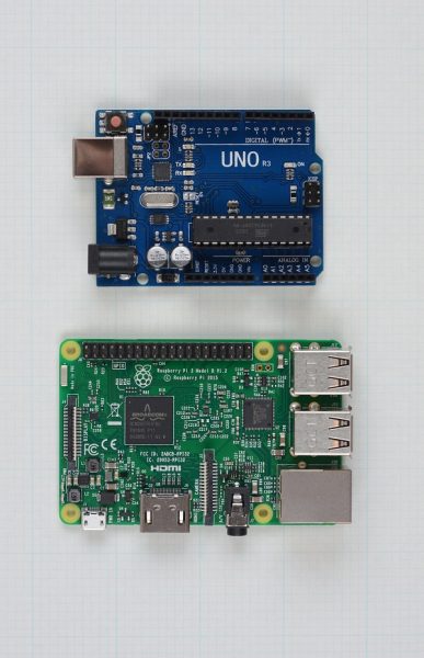
Fig. 1
Some industrial users might imagine these microcontrollers as a substitute for an entry-level PLC. In the Control Design August 2017 cover story Arduino vs. PLC for industrial control, author Doug Reneker says, “If an Arduino can control a robot for a STEM competition entry, why can’t it control an industrial robot, or a simple machine? If it’s possible to buy an Arduino for as little as $20, why spend hundreds on a PLC? An Arduino can do lots of things, but as I discovered, making it work in even a simple industrial application is easier said than done.” Doug Reneker is a circuit designer, recently retired as a senior manager at Arris, a provider of broadband communications equipment for internet providers and consumers.
This article compares automating a simple flow loop using an Arduino microcontroller, and then with an AutomationDirect BRX PLC. While the microcontroller may be able to do the job, additional hardware and significant program development is required. A purpose-built industrial controller, such as the AutomationDirect BRX, can do the job much more easily.
Real-time Control with an Arduino
According to the Control Design cover story, the Raspberry Pi is effectively a miniaturized Linux-based single-board PC, whereas an Arduino is more like a PLC in some respects. While either platform looked suitable, Reneker settled on the Arduino for this project, which is closed-loop control of flow generated by a pump. A sensor measures flow and sends data to the Arduino, which adjusts a control valve actuator to maintain the setpoint. This is one of the most basic industrial analog automation functions, and often uses a PID loop as the control algorithm, says Reneker in the cover story.
The application requires just PI control capability because reading a process variable from a flowmeter and adjusting a valve to reach and maintain a setpoint does not typically require use of the derivative in the PID equation. It’s a simple control loop, but using an Arduino in a real-world industrial process can get complicated.
“The Arduino is a bare-bones device, as befits its price, but it does have extensive capabilities if the right program can be written to match the application,” notes Reneker in the cover story. “It’s a totally blank slate for a programmer, with no native capabilities or function blocks ready to upload,” he says. Not only did he need design and build hardware to connect to the instruments, he had to create the PI algorithm from scratch using Arduino programming.
The Arduino includes discrete and analog I/O, but the signal types and ranges are limited. Analog input range is 0-5 V, and the analog outputs are pulse-width modulation (PWM). While these limited signal levels work for regulating motor speed or modulating a temperature control loop, they are not the most common range for typical industrial applications. A common industrial analog signal level is 4-20 mA current, the standard used in the demonstration project. This required a significant design effort for implementation with the Arduino.
Don’t Take Current Loop for Granted
According to the Control Design cover story, the demonstration equipment uses standard off-the-shelf industrial components: a Rosemount 3051SFP Integral Orifice flowmeter and Fisher Easy-Drive control valve, both provided by Emerson Automation Solutions (Figure 2). These were not selected for any specific capabilities or characteristics beyond their physical size. They are both very common types of components, making them very appropriate for this demonstration.
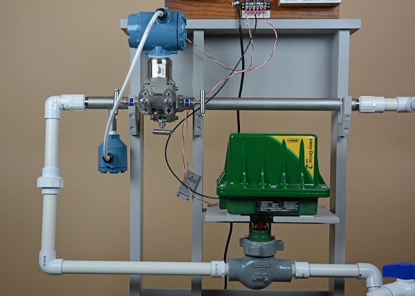
Fig. 2
“The first step is converting the 4-20 mA signal coming from the flowmeter to 0-5 V, or better, 1-5 V to retain the live zero,” explains Reneker in the cover story. “This is not an uncommon situation, and converters are available from multiple sources. However, in keeping with the DIY character of the experiment and to keep costs down, I created one from scratch (Figure 3). It was built on an Arduino prototype shield to mount on top of the main board. A simple 250-Ohm resistor converts the 4-20 mA signal to 1-5 V.”
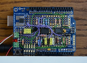
Fig. 3
A challenging task when using an Arduino in this industrial application was converting the PWM analog output to 4-20 mA. “The lack of commercial solutions suggests this isn’t a common conversion, so I had to build this converter from scratch,” says Reneker in the cover story. “I decided to electrically isolate the 4-20 mA current loop output using a two-channel optoisolator to allow more flexibility in connecting with other current loop devices Figure 4. This leaves the problem of powering the circuit, as it is isolated from the power supplies. This was solved by powering the circuit from the current loop itself, using a voltage-reference integrated circuit.”
A low-pass filter was used to filter the Arduino’s 500 Hz PWM analog output and relating harmonics. The filter provided a dc signal proportional to the duty cycle of the PWM signal. An op-amp then converted the low-pass filter output to a current.
Adding to the Stack of Hardware
In the cover story, it was noted that an Arduino has no power supply, nor does it have any type of human-machine interface (HMI), but it can use a small graphics display “shield” added to the stack of devices, with a screen size of about 1.75 by 2.25 inches (Figure 5). Adding an HMI to the Arduino requires custom programming to display useful information. With a PLC such as the AutomationDirect BRX, several HMI hardware choices are available, with each only requiring simple screen configuration.
Terminating wiring to the Arduino required extra hardware and tools. While the supply power was connected to terminals, I/O was not a simple terminal and screw connection. Small gauge wires, crimp terminals, a crimp tool and three different width (pin count) electronic header connectors were needed. Mounting the Arduino boards also required some custom mounts as there is no commercially available Arduino enclosure with an industry standard DIN-rail mount.
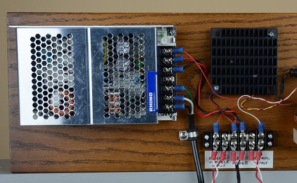
Fig. 5
A standard 24 Vdc power supply powered the flowmeter and control valve in this demonstration project, but the Arduino doesn’t accept this standard voltage level. A linear regular was needed to regulate the 24 Vdc down to the 12 Vdc required by the Arduino.
Time to Program
Reneker briefly described how he wrote the PI algorithm and simple display program in the Control Design cover story. “Writing code to implement the PI algorithm on the Arduino had to be done from scratch but was relatively simple,” he says. “The current loop input is read, the difference between the setpoint and the input evaluated, the integral and proportional corrections are calculated, and the result is sent to the PWM current loop output.”
According to the cover story, to view operation of the control circuit, Reneker “wrote a program to use the small display to indicate both the process variable—read via the current loop input—and the control output as a function of time. This provides a direct view of the performance of the control system.”
There were additional analog inputs available so three potentiometers were connected to provide adjustable operating parameters. This included a water flow setpoint and the P and I action – the proportional and integral gains for the control loop – to adjust stability and response time (Figure 6).
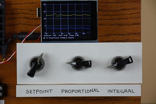
Fig. 6
Arduino Process Control
The flowmeter included a local display indicating a gallons-per-minute flow rate and an inches-of-water differential pressure across the meter, providing a simple indication of loop operation. “The PI algorithm performed as expected, and the loop can be tuned by manipulating the potentiometers to adjust the two control factors,” says Reneker in the cover story. “Flow control exhibited the normal characteristics, good and bad, of PI loops.”
Reneker used a flow bypass valve to force changes to the process, requiring the control loop to adjust the flow control valve to maintain the setpoint. He also created a program for the Arduino display to display a trend of the control loop (Figure 7). However, the display is very small and would be difficult to read in a factory application.
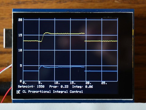
Fig. 7
After running the demonstration project process, Reneker found the custom PWM-to-current-loop converter he built was the main bandwidth limitation. “The necessity to use a low cutoff frequency to adequately filter the PWM limits how fast the Arduino can respond to a change in conditions,” says Reneker in the cover story. “The 100 ms (10 Hz) sampling interval works well, once the proportional and integral gains are adjusted. If the bypass valve is open, it robs roughly half of the input flow from the system, but the Arduino adjusts the control valve to achieve the desired flow within a few seconds. With steady water flow, the system is stable, without any indication the control valve is making adjustments.”
The Arduino did okay controlling the simple loop control in the demonstration project, but it didn’t inspire confidence for use in a real factory. If it was properly designed as an industrial-grade controller, like a PLC for example, it would be able to handle continuous operation inside a control enclosure on the plant floor. It needs to survive the heat, cold and vibration. The Arduino doesn’t seem to have been designed with this type of operation in mind as it appears quite fragile. Its use on the factory floor should be carefully reviewed, even if and when industrial-strength Arduinos emerge.
Industrial-Grade BRX PLC
For comparison, the second part of the demonstration project used a PLC, in this case a BRX Series PLC (BX-DM1E-10ED23-D) from AutomationDirect, to control the process loop (Figure 8). This is an objective comparison between an Arduino controller and a PLC because Reneker had no prior experience with PLC programming or knowledge of ladder logic. Implementing the BRX in this application would have been much easier for an experienced PLC programmer.
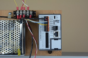
Fig. 8
The AutomationDirect BRX controller has the ability and reliability to execute the many logic operations and communication requests often needed in industrial applications. Although not used in this demonstration project, the BRX series controller can provide data logging, motion control, high speed I/O with processing, and customizable communications to meet the demands of industrial automation machines and process.
The BRX PLC has one analog input and one analog output (current/voltage selectable), along with a mix of 10 discrete I/O points. All connections are through removable terminal blocks on a 5-mm pitch. Analog and discrete expansion modules are available but were not needed.
The BRX also includes a built-in Ethernet port. This provided easy programming access, via Ethernet, between the PLC and Windows-based PC running the Do-more Designer software. This full-featured software programming tool for Do-more CPUs such as the BRX can be downloaded free at https://support.automationdirect.com/products/domore.html
PLC Configuration and Communication
With the software loaded on the PC, it was connected to the PLC via Ethernet. 24 Vdc power was also connected and applied to the PLC. The Ethernet IP address of the PC was determined using the ipconfig command. The Do-more Designer software was then used to give the PLC a unique IP address on the same network subnet.
As noted in the cover story, Reneker was not familiar with ladder logic, so he needed to learn it. “Chapter 10 of the BRX PLC Hardware User Manual includes a step-by-step example of programming a simple timer using ladder logic,” says Reneker. “Working through this exercise provided a nice introduction to the software and to the basic programming structure of the PLC.”
Instead of designing and building a custom PWM-to-current analog output interface, as needed for the Arduino, the Do-more Designer software provided a simple, fill-in-the-blanks configuration window to set the analog output to 4-20 mA. A couple of rungs of ladder logic were created, and then the analog output function was quickly verified with a multimeter.
The PLC includes a modular, interchangeable and run-time configurable PID instruction. This efficient logic instruction provides easy to access parameters such as filters, scaling, ramp-soak tables and alarm handlers. Instead of buying a display and custom programming a trend screen, which was required with the Arduino, the PLC’s PID trend views graphing the control loop response can be viewed on the PC, saving time with tuning and troubleshooting.
“The PLC offers a sophisticated PID instruction, allowing the various loop parameters to be set for manual or automatic control of the loop,” says Reneker in the Control Design cover story. “A very simple control loop was created by connecting the analog output back to the analog input, again using the milliammeter. Associating the PID instruction with the scaled analog input and output allowed the PLC to learn the PID function without handling several gallons of water. Active PI control was verified by “robbing” a bit of the output current with a resistor and watching the BRX PLC compensate.”
It was simple to integrate the analog signals to the PLC. For the analog input to the PLC, 24 Vdc was added to the flow sensor current loop. The PLC analog output provided the loop power, so it was connected directly to the control valve.
The system was turned on, and, to achieve stable flow through the system, the Do-more Designer software was used to adjust the PID instruction’s proportional and integral coefficients. The flow setpoint was adjusted by simply changing a floating-point variable in the PLC’s data table using the software. The Do-more software was used to provide real-time monitoring of system performance using self-scaling plots of both the process and the control variables.
Reneker notes in the Control Design cover story, “Beyond the basic, core level of operation, the PLC offers a wide variety of the common support functions often needed in an industrial application such as limit detection, reporting and data recording. Compared to our Arduino demo, where each function must be written from scratch, this PLC allows the system designer to focus on the application and how it fits into a larger production system, instead of the details of controller hardware and software.”
The Choice is Easy
“So, which is better, the Arduino or the PLC,” asks Reneker in the cover story? “If only bare hardware cost for the controller and I/O are considered, the Arduino wins. But when all the ancillary components necessary to make the Arduino useful in this relatively simple application are added, the hardware cost gap will narrow or disappear. The time necessary to assemble and program the Arduino is also considerable. When this time is calculated at anything near normal engineering man-hour rates, the PLC is the clear winner in terms of overall cost.”
Regarding function and performance, the Control Design cover story shows the Arduino and the PLC got the job done. However, it also notes that this is just a simple flow control loop. Typical industrial applications include many other discrete and analog functions. This is a strong point of a PLC as many functions are built in, and I/O expansion capabilities are extensive. This functionality and expandability is not included with the Arduino, unless you do the work to create the hardware and software.
The best programming method often depends on the user’s background. An experienced C language programmer will likely find the Arduino a quick study. However, all functions, even the most basic, will need to be custom coded from scratch. Ladder logic programming may take some time as well, depending on the user.
The cover story notes, however, that the number of online and other tutorials available for PLC certainly weighs in its favor. The AutomationDirect website has many videos and tutorials aimed specifically at industrial users. “There are many function libraries available for downloading to perform common operations,” notes Reneker. “For example, the PLC has loop-tuning software available, which would be very complex to write for the Arduino.”
It’s clear, from an equipment durability standpoint, that the PLC is much more suited for industrial applications than the Arduino or Raspberry Pi. The BRX PLC is also part of AutomationDirect’s product line, providing long-term support along with scalability, built-in capabilities and ease of expansion. Additionally, a quick look at the expansion I/O modules, operator interfaces and other made-to-integrate hardware makes the BRX PLC an off-the-shelf and time-efficient solution.
Reneker sums it up well at the end of the Control Design August 2017 cover story. “For someone learning the basics of code writing and concepts of control, the Arduino and its ilk provide interesting teaching tools. Having to write control algorithms from scratch causes a user to consider the intricacies of how automation is performed. The availability of devices with this level of sophistication at such low costs is quite remarkable and is a boon to those with more time than money.”
But for an actual industrial application where production and revenue are at stake, says Reneker in the cover story, “a PLC with equivalent or better capabilities can be had for a few hundred dollars, and it will come with extensive online training videos and other information, and with function block libraries designed specifically for industrial applications.”
FIGURES, ALL COURTESY OF PETER WELANDER AND DOUG RENEKER
*Originally published: Nov 8, 2017