Arduinos and similar devices can be highly versatile but are too delicate for industrial environments. We test a new version designed with a tougher form factor.
Byline: Doug Reneker
In two previous project articles, we set out to prove that single-board controllers, common to the maker community, can be adapted to industrial applications. Or it might be as accurate to say industrial applications can be adapted to work with such controllers. In the first project, an Arduino was able to control a flow loop using PID control, and for the second, a Raspberry Pi was able to perform model-based temperature control.
Some of the problematic characteristics of these devices have proved to be their physical fragility and the difficulty of making connections. These small controllers are, for the most part, naked boards (Figure 1) with exposed contacts, and protecting them sufficiently to survive in an industrial environment is the responsibility of the user.
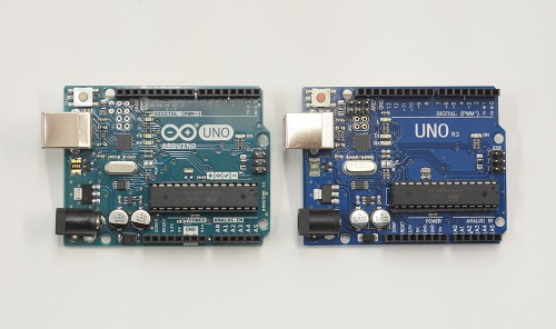
Figure 1: An Arduino is a powerful and versatile controller, but it is fragile and making connections can be difficult.
To solve this issue, there are now industrialized versions of these controllers, built into the kinds of housings and form-factors more typical of conventional PLCs and supporting modules. These provide much simpler assembly with DIN-rail mounted modules and power supplies. One example is from AutomationDirect, offering the ProductivityOpen P1AM-100 Arduino MKRZero -compatible controller in an industrial enclosure. The ProductivityOpen interfaces with other AutomationDirect communication and I/O devices to support connectivity common to industrial control panels.
So, the challenge for this project was to create an industrial type of application using an industrialized Arduino and associated components, to see what advantages they offer over conventional maker hardware.
A High-Wattage Soldering Station
This industrialized Arduino project has the advantage of demonstrating the hardware concept while also providing a useful piece of equipment. As part of another project, I have been designing and building a power supply that needs a transistor soldered to a copper heat spreader that is far too large to heat with a soldering iron. A propane torch could to the job but is difficult to control and could easily destroy the transistor.
Considering some other options, a common hot-air heat gun has a lot of output—about 1500 watts—which is substantial compared with a 50 to 200 watt soldering iron. By building a tabletop (Figure 2) with some stainless-steel hardware cloth in the middle, it was possible to mount the heat gun underneath to direct heated air directly on the copper plate. This gets it hot enough, but the problem is providing a controlled, steady temperature. This application could be solved using a conventional temperature controller, but for the sake of the demonstration, we’re building it from scratch using the Arduino-type controller.
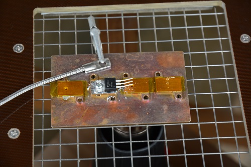
Figure 2: The demonstration project is designed to heat the workpiece and facilitate soldering components to a large copper piece by using a hot-air gun positioned under the table as the heat source. Hot air blows up from below onto the workpiece.
As one of the demonstration objectives, we used conventional proportional integral derivative (PID) control, which is common for all manner of closed loop applications, including temperature control. Proportional control drives the temperature to a desired setpoint. Integral control compensates for errors due to limited proportional gain. Derivative compensates for thermal lag between the heater and the temperature sensor, avoiding overshoot.
Hardware Selection
An Arduino-based controller can easily handle the data-processing needs of this system when provided with an accurate temperature measurement of the copper plate using a thermocouple or resistance temperature detector (RTD). In this case, we are using the former, but it needs precision signal processing to provide a useful temperature reading.
The ProductivityOpen P1AM-100 CPU is supported by the Arduino Integrated Development Environment (IDE). This means the CPU interfaces with the Productivity1000 series communication and I/O modules, as well as the maker-oriented interfaces (shields), so hardware can be mixed as needed. More on that in a moment.
Adding a P1-04THM temperature input module (Figure 3) provides the interface and data processing for a type J thermocouple. The sensor attaches directly to the copper plate to provide robust and responsive temperature data. The P1AM-PROTO prototyping shield is used to support additional bits of circuitry described below, and adding a bracket and two DB-9 connectors simplified the necessary connections. Since all these modules mount on a standard DIN rail and have integrated interconnects, packaging is neat, modular, and sturdy.
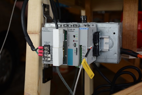
Figure 3: The thermocouple sensor signal is processed by a temperature input module that sends characterized data to the main controller CPU, while a prototyping shield enables other display and I/O functionality.
The heat gun is controlled using a zero-voltage switching solid-state relay, driven by a digital output pin from the CPU to turn the gun on and off on a cycle-by-cycle basis to throttle its output. To keep an accurate account of cycle-by-cycle control, the AC power line phase needs to be sensed by an input pin to the CPU, to time driving the solid-state relay. Optoisolators protect both of the CPU pins from transients and external faults.
To maintain workshop safety and prevent the system running unattended, there is a footswitch in series with the solid-state relay control signal, so the operator must be physically present with a foot on the switch for the heat gun to operate.
Finally, a mechanism for data display and control is included to avoid the need to have a laptop available when operating. For this, a maker-community device works with the industrial hardware, proving the ability to mix sources. An Adafruit #772 16 x 2 LCD display, with pushbuttons and an I2C interface connects to the CPU using only two digital pins to drive the display and scan the pushbuttons. A block diagram (Figure 4) summarizes the hardware arrangement.
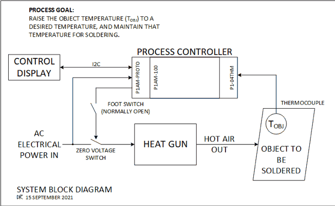
Figure 4: The system block diagram shows all the operational components.
Writing Control Code
ProductivityOpen offers two approaches for programming. ProductivityBlocks is a graphical front-end to the Arduino IDE, allowing the programmer to drag and drop control constructs (loop, if then, else, etc.), as well as providing access to CPU I/O and Productivity1000 modules. It generates a “sketch” (program) in the IDE, which gets compiled and uploaded to the CPU. Using ProductivityBlocks avoids common syntax errors, such as missing or extra braces, or a missing semicolon.
The alternative is to write directly in C or C++ within the IDE. Based on familiarity and experience with this method, this is our choice for the project.
A series of functional software blocks were developed incrementally. The first controls the heat gun, including power line sensing and solid-state relay control. Since zero-voltage switching is used, the heat gun must be either on or off for a whole cycle of the AC power line. The power line discrete input generates an interrupt for each cycle of the 60 Hz AC, and the throttle code executes in this interrupt routine, 60 times per second. We can define the range of the throttle for 0% to 100%.
The throttle setting defines how many cycles the heat gun is on out of 100 cycles, which is also known as time-proportioned control. A table with 100 entries maintains a count of the most recent number of cycles the heat gun was on. For each new cycle, if the desired throttle is greater than this count, then the heat gun is turned on for that cycle, and the count and table are updated. Similarly, if the desired throttle is less than the count, then the heat gun is turned off, and the table and count are similarly updated. If the count and throttle are equal, then the gun is turned on or off based on the table contents. In operation, the heat gun pulses on and off in an odd way but quickly enough to provide reasonably steady heat.
The thermocouple interface uses a program from the standard library provided with the CPU extension to the Arduino IDE. The thermocouple input module is very flexible, and requires a set of numeric parameters to use. Rather than reading a detailed manual to figure out how to choose each parameter, a website (https://facts-engineering.github.io/modules/P1-04THM/P1-04THM.html ) includes a tool to determine the necessary parameters based on the type of temperature sensor and its operation. These can be copied and pasted into the Arduino sketch yielding a very simple program that works in a matter of minutes.
The last interface is the LCD display and pushbuttons. The CPU doesn’t reserve the pins used for the I2C interface, so the standard Arduino I2C library (Wire) can be used. Adafruit supports it using Adafruit_RGB_LCD_Shield_Library to control the display via I2C using the Wire library.
One common challenge when mixing industrial and maker hardware is resolving voltage mismatches. The LCD display operates at 5.0 V, and uses 5 V signaling on the I2C interface. The P1AM-100 interfaces to 3.3 V, and can’t handle 5.0 V signals. Shifting level in this situation is critical since I2C signals are bi-directional, without explicit signals to control the direction.
Fortunately, a low-threshold MOSFET transistor can be used to provide the necessary level shifting function. SparkFun electronics sells a suitable level shifter (BOB-12009), but for the project, we chose to build the level shifter from scratch, in the prototyping module. An old Philips Semiconductor application note AN97055 (available at https://cdn-shop.adafruit.com/datasheets/an97055.pdf ) goes into the electronic details. With the level shifter in place, the HelloWorld.ino example program in the LCD library runs nicely.
Application Code
With all the control interfaces working, the next step was creating application code. This involved creating some code to perform the PID algorithm. As anyone who has tried to tune a PID loop knows, loop effectiveness depends entirely on the coefficients used for the proportional, integral, and derivative values of the control equation. Given the imponderables in this system, such as the thermal coupling from the heat gun to the object, the thermal capacity of the object, and the delay in thermocouple response, an easy way to adjust these coefficients is needed. Otherwise making a change to the program itself requires re-writing, re-compiling, and re-loading the software for each adjustment. Also, the desired temperature setpoint must be adjustable.
Once these factors are set up, the operator starts and stops the control algorithm as required. By writing a simple state machine, it is possible to cycle through each of the settings via the left and right buttons, while adjusting parameters with the up and down buttons. The select button is used to start and stop the PID control.
Two lines of 16 characters can display all the necessary information (Figure 5). This includes the actual temperature (top left), with the setpoint shown immediately below. The throttle setting is shown (bottom center), along with the current state of the state machine (bottom right). If a parameter is being set, its value is shown on the top right.
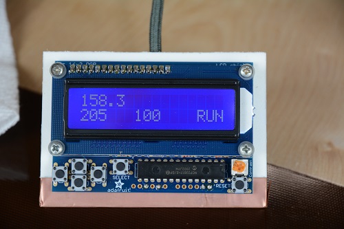
Figure 5: A simple display shows the actual temperature, setpoint, heat-gun output, and operational state. The pushbuttons allow the operator to change all parameters.
With all the software working, full operation was now possible. The heating system worked as expected, but with a significant lag common to temperature control applications (Figure 6). With the initial PID factors in place, the loop routinely overshot the setpoint by 7 to 8 C. Recovery from the overshoot resulted in a subsequent temperature undershoot, and oscillation of several degrees C around the desired setpoint.
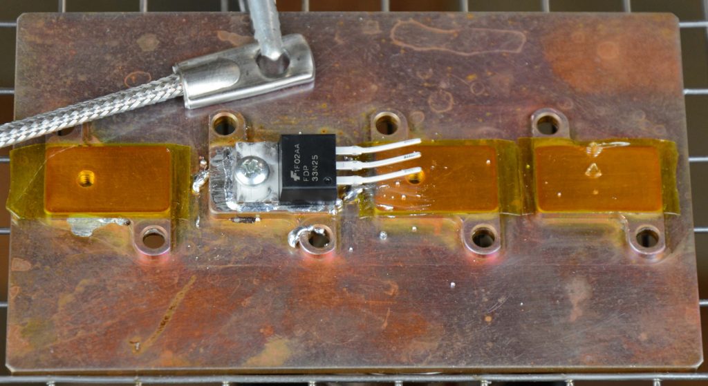
Figure 6: A thermocouple attaches to the copper piece using an alligator clip to measure its temperature during the heating and soldering process. The plate’s desired temperature was maintained properly after some PID adjustments within the controller
Fine tuning the PID loop, and making some adjustments to optimize control for this application required some additional work, which would have been required regardless of the type of controller used. See the Sidebar “PID loop operation and tuning” to find out the approach that worked in this case.
******************************
SIDEBAR: PID Loop Operation and Tuning
Basic PID operation has been covered by many others. Temperature control can be particularly vexing due to the long delay between heater control and the response of the thermocouple involved. The common solution is increasing the derivative factor to slow the temperature increase and avoid overshooting. With a higher setting, the controller reduces the initial overshoot, as the copper heats up from room temperature. It throttles the heater back as the setpoint is approached. A derivative coefficient, roughly double the proportional coefficient, proved effective in this case. Unfortunately, this change reduces stability, causing the variable to oscillate around the setpoint.
Another problem is the integral coefficient. Since the equipment starts at ambient temperature and must reach a typical soldering temperature of 200 C, the initial heating takes several minutes, causing a huge stored integral term to build up. This must be overcome by the derivative coefficient to avoid overshooting the setpoint. Since the proportional coefficient is sufficient to turn the heat gun 100% on at the beginning, the integral term adds no value during initial heating.
At the same time, the integral term helps maintain a steady temperature near the setpoint. The proportional part of the algorithm has limited gain, which means that some residual error relative to the setpoint is needed to keep the heat on to maintain soldering temperature. The integral factor of the algorithm compensates for this, by adjusting and storing an integral adjustment. It turns out that relatively little throttle is needed to maintain temperature. At the same time, since the copper is hot relative to ambient air, it cools down on its own fairly quickly. This is important since the heater can only push the temperature up – it has no mechanism to cool the workpiece if it is too hot.
Two tweaks to the integral control solve this problem. The integral factor is allowed to contribute no more than 30% to the overall throttle setting. This limits how much the differential term needs to overcome on initial heating. Also, the integral factor is not allowed to go negative. It can only be a positive contribution to the throttle. Thus, the integral part of the control equation is only effective when the temperature is at or a little below the setpoint, which is exactly the behavior needed.
Another characteristic is that when the controller turns on the heat gun, it initially blows cold air until the internal heating element warms up. So, a sudden increase in the throttle (from 0 to 100%) can cause a temperature drop of a couple of degrees before the temperature starts to increase. This is a major cause of temperature oscillation around the setpoint. In steady-state operation, some continuous heat input is needed to maintain soldering temperature. Adding a minimum throttle parameter, around 10%, is less than the heat needed to maintain the object at soldering temperature, but enough to keep heating element primed. This minimum throttle parameter is adjustable, along with the setpoint and PID coefficients.
After several hours of tuning the PID coefficients, and introducing the tweaks just mentioned, the soldering heater works very nicely. Initially the throttle goes to 100% to heat the object as quickly as possible. As the temperature approaches the setpoint, the heat gun throttles back, and the object coasts up to the desired temperature with little overshoot. Added puffs of heat maintain the temperature within a degree or so of the setpoint, which is quite adequate for soldering. The controller does its job exactly as designed.
******************************
Why use this controller?
To answer this question, we must think about this demonstration not as a temperature controller, but that it represents any kind of small-scale controller project. What are the other alternatives?
A conventional Arduino has many capabilities, it is inexpensive, and it is easy to program using C or C++. To many engineers, this is a very clear choice, but not without its drawbacks. First, as mentioned earlier, the physical fragility. Second, various interfaces, such as reading a temperature sensor or other type of industrial instrument, must be built from scratch. (The first project article illustrates this situation in greater detail.)
A small PLC can also handle the necessary control requirements, and it will have accessories designed to act as interfaces to those external devices along with power supplies. It will also be more physically robust and easier to assemble using standardized interconnections and DIN-rail mounts. A PLC has more robust software with background utilities that identify when problems are developing, and can warn the operator or shut down to a safe state. These capabilities are not part of the native Arduino IDE. The main downside of a PLC in this context is its higher cost combined with its ladder-logic programming environment, which is foreign to a typical maker.
An industrialized Arduino, such as the AutomationDirect ProductivityOpen, is a useful compromise between those two extremes:
- Industrial form factors overcome the fragility of unprotected boards and simplify connectivity.
- Modular interfaces for industrial sensors and peripherals are available.
- Hardware versatility allows use of industrial and maker devices, including DIY adaptations.
- Programming using C and C++ is possible, along with other platforms, including ProductivityBlocks.
However, the lack of protective and housekeeping software functions available from a PLC should give an engineer pause to ask, “What could potentially happen with this system if the controller fails?” An engineer considering a small-scale project such as the one here has some critical questions to ask, but it is always helpful to have the widest variety of options available.
About the author:
Doug Reneker is a retired electrical engineer and circuit designer who worked for Bell Labs, Recon/Optical, and Arris. He has a BS and MS in electrical engineering from Iowa State University. Contact him at reneker@ieee.org.