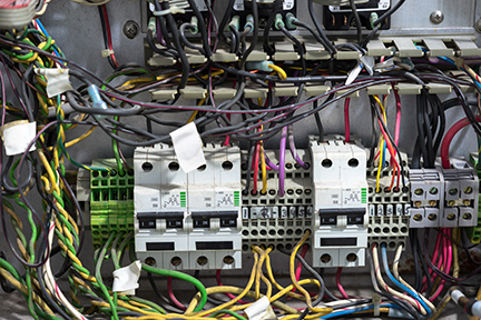
In a Control Design September 2018 Automation Basics column titled “Terminate the Rat’s Nest”, author Dave Perkon gets right to the point when he writes, “For those who think it’s okay to open a control enclosure and see a monochromatic rat’s nest of wires without any wire labels, you should be aware, that’s worst-case practice.”

To make sure this doesn’t happen, there are many standards to follow, but for some reason, many panel designers and builders go their own way. As Perkon writes in his column, “Whether it’s the lack of experience of the designer and builder, or the OEM thinks it’s OK to do it that way to save money or someone is just being lazy, messy control-enclosure wiring and lack of wire labels are just a job done poorly in the world of industrial control systems. When it comes to terminating I/O and power wiring in a control enclosure, there are basic standards that must be followed. just about any industrial-equipment user should require suppliers of control systems and control panels to follow some control-panel-wiring best practices. A good source for these wiring practices and much more can be found in NFPA 79: Electrical Standard for Industrial Machinery, 2018 edition.
While it’s just one of many standards automation engineers should use, NFPA 79 is a must-have for any machine builder, OEM, system integrator or any end user with automated machines. It provides control-design standards and how to install electrical equipment properly to protect operators, equipment and facilities from electrical hazards and fire.
Field Cable Routing
The column points out that proper I/O termination does not just include where the wire is connected to the terminal in the control enclosure, it starts in the field where the cable must be properly routed and supported. The field cables, external to the enclosure, should be attached to the machine frame. These field cables combine into large cable bundles, and both individual cables and cable bundles should be supported or attached to the frame every 12 inches.
The machine, equipment or its operation may damage cable—so wiring and cables need to be protected. “Cable routing provides long-term protection, so don’t attach the cables to machine guarding that may be removed,” says Perkon in the column. “Also, if a damaged sensor cable must be replaced, as part of a bundle of cables, cut all the cable support ties, remove the faulty cable, replace the sensor cable and then reinstall the cable ties while keeping the cables parallel in the bundle, not woven-like.”
The author also points out that field wiring should be neat and well maintained. “The rat’s nest may be outside the control enclosure. By not reinstalling the cable ties and just strapping the new cable to the outside of the existing cable bundle or leaving the faulty cable in the bundle, the technician is just creating a mess that only gets worse over time. A poorly done repair, with the excuse that it was quicker, is a worst-case practice.
The Landing Strip
Once the field cable enters the enclosure through a suitable cable gland or conduit fitting, it cannot just be terminated to an internal device such as a power supply or motor starter. Instead, it must pass through a terminal strip. Just as breakers and fuses must be properly sized for the expected ampacity, terminals must be properly sized.

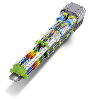
The DINnectors DIN rail mounted terminal blocks shown left are available in single-level, double-level, triple-level, sensor, mini, grounding, fuse holder, disconnect, plug-in, thermocouple, test plug and direct mount configurations to meet various wire termination needs.
These terminal strip devices are mounted on a DIN rail. It is good design practice to surround the terminal strip with wire duct to help manage the wires and cables, so the DIN rail is often raised. Not using wire duct around a terminal strip can cause a sagging tangle of wires. Not raising the DIN rail will make it difficult to connect wires to the terminals as the wire duct can block access, depending on its height.
“There are very few instances where a terminal, as part of a terminal strip, is not used to connect all field wiring, stresses Perkon in the Control Design column. “Field wiring does not attach directly to relays, input/output modules, safety devices and drives; it typically passes through some kind of terminal first.”
Different types of terminals have different applications. In his column, the author suggests that “Single-level terminals work well for miscellaneous terminations within the enclosure and some power distribution. Double-level terminals work well to terminate discrete output signals with one level for the output and one level for a bussed common. It’s also a good way to distribute 24 Vdc power. Triple-level terminals work well to terminate discrete input signals, providing an input terminal and terminals for +24 Vdc and 24 Vdc common, often needed for sensors.”
Perkon also notes that analog I/O terminations benefit from multi-level terminals to address needs for loop-powered or self-powered transmitters and cable shields, which must also be terminated.
Wiring Terminations
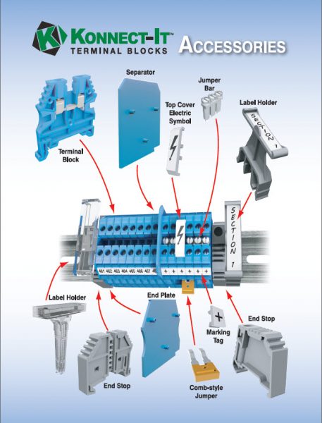
Some of the author’s final notes on eliminating the rat’s nest include the following. “Wires do not pass over the top of terminal strips; they go around, using the wireway. And in no cases are splices, wire nuts or solder connections allowed to stretch a wire in the duct—add a connector.” Accessories should be used as required including separators, end plates, jumper bars, comb-style jumper, label holders, marking tabs and end stops.

The Control Design column also included wiring basics. “Each cable or wire connected to the terminal strip must be labeled to match the electrical schematic. The terminal strip should also have a label on the back panel, such as TS1 (terminal strip 1).
Along with labeling that matches the schematics, it is important to use the correct color wire. Field wiring often uses multi-conductor and multi-color wiring. Discrete wiring inside the control enclosure and field cables, such as 3-wire sensor cables, should follow NFPA 79, NEC 70 and UL 508A standards. These North American Codes are harmonized where they overlap among the field, machine and cabinet levels.
Multi-conductor cables often have black conductor insulation with white printed numbers, although some are multi-colored, and there is often a green/yellow insulated ground conductor, all inside a gray jacket. Two- and three-wire sensor cables are moving to an international color code. Pair cable often includes a black and white wire, while 3-wire sensor cables include a brown, black and blue wire. It depends on the sensor, but the brown wire is typically 24 Vdc, the blue is 24 V common and the black is the signal. Four-wire cables add a white wire, often a signal wire as well. The cable shield is often a braid or foil and includes a tinned copper wire.
Each of these cable conductors from the field should be terminated at the cabinet terminal strip. This includes the shield, which may be grounded at the terminal connection or isolated from ground as it passes through the terminal to a control panel device. If some of the cable conductors are not terminated at the terminal, they should be tied back and treated with a heat shrink—as clearly stated on the electrical schematic that details the connections.
Read more article about terminal blocks and wiring here!
*Originally published: Nov 7, 2018

