
So what do you think, is this glass half full or half empty? For me, that could be a little difficult to answer and could vary based on the day I’m having, but if we are asking about the level, why not let the PLC answer? In fact, why not have the PLC tell us the level, the temperature of the water, the flow rate at which it was filled, the available capacity of the glass and the pressure exerted on the bottom? Ok, normally you wouldn’t use a PLC for such a small application, but on a larger scale, say a reservoir, it is possible for the PLC to answer all of those questions. But how can we make the PLC even “see” this reservoir, let alone tell us how full it is? Well I’m glad you asked, or I asked, or whatever. We need a device that can allow the PLC to take information in from its surroundings and process it. We also need a device that will allow the PLC to affect its surroundings as needed. What we need is I/O, and what I mean by I/O is Inputs and Outputs. For this discussion, we’ll focus on the two main types of I/O: analog and discrete.
Discrete I/O
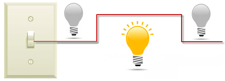
Let’s take the simplest first, discrete. Discrete signals are signals that are either on or off, true or false. Think of a light switch in your house. The switch either turns the light on or it turns it off, unless it is a florescent tube – then it’s probably still blinking. Because discrete signals exist in one of these two states, they are represented with a square wave as seen below. In the PLC world, there are many uses for discrete I/O. Some of the devices that supply on/off signals are pushbuttons, photoeyes, limit switches, float switches and proximity switches. In my startup days, I did a lot of work with a certain parcel service. They use a lot of on/off sensing and control in order to track packages and get them to the right destination or truck. Photoeyes, which are devices that emit an infrared light beam and can sense when that beam has been broken, are used extensively to detect and track packages through their sorting process. The application of your control system will determine the types of discrete devices you choose. There are a variety of discrete end devices and modules that can be used in a PLC system to send and receive on/off signals. These devices can be AC or DC and are available in different voltage ranges. 0-24VDC and 0-230VAC are two voltage ranges available, with 0 being the OFF signal and 24VDC or 230VAC being the ON signal. Usually there is a threshold for detection, where the 0-24VDC module will detect anything over 22VDC as the ON signal and anything below 2VDC as the OFF. Now let’s look at analog.
Analog I/O
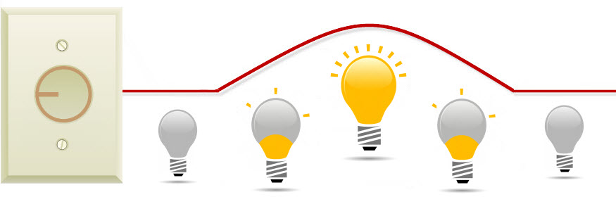
Analog signals are signals that can vary or change. We live in an analog world and our senses are analog receivers. “Feel how hot it is!”, “Can you speak up?” and “Look at all the colors!” are statements that show how the variation in analog signals like temperature, sound, and light can affect our senses. Back to the light switch example; let’s now install a little mood lighting in our home. Instead of the regular on/off switch we are going to use a dimmer switch. The dimmer switch will vary the resistance in the line, causing the light to dim or brighten as we choose. Newer dimmer switches have advanced to be more efficient but for this example we are going old school. The voltage supplied to the light will not be a constant level but a changing one set between the upper and lower limits. This is usually represented by a sine wave.
Using Transducers

Position, level, temperature, pressure, flow and speed are just some of the measurements that analog devices can provide to a control system. You are probably asking yourself: “How does pressure, which is a physical quantity, become an electrical signal?” That is a great question! The conversion is done using transducers. A transducer will take a physical quantity like pressure and convert it to an electrical signal. A lot of transducers use the physical quantity to control the resistance in the electrical circuit. For example, an RTD (Resistance Temperature Detector) will change its resistance value based on heat. As heat increases so does the resistance in the circuit, altering the supplied voltage or current. Same holds true for pressure transducers that use strain gauges. As pressure is applied to the strain gauge, the resistance in the circuit goes up and the voltage or current level changes. Some flow detectors will use the flow of a fluid to push a fin that is connected to a rotary potentiometer. Faster flow equals more resistance change. One of the coolest transducers that I ran across in my days working in the offshore oil industry was the sand detector. This transducer was acoustic and was attached to pipes that were drawing oil out from the sea floor. It would actually listen for sand rubbing against the inside of the pipe. The amount of sound was converted into an analog signal used to alert personnel if the drilling was drawing out too much sand, which could collapse the well. The electrical signals that transducers provide can be voltage or current based. 4 to 20mA, 0 to 20mA, 0 to 10VDC and -10 to +10 VDC are a few of the available ranges produced by transducers. The PLC supplies the voltage or current and the transducer will return a value in its configured range. That value will be proportional to the amount of pressure, flow, etc. that is present. We now arrive at two important parts of this discussion: scaling and resolution.
Scaling
Scaling is when we take the raw voltage or current value returned and translate it into a meaningful measurement. Let’s say I have a 4-20mA flow meter that is returning an 8mA signal to the PLC. That would mean that 8mA of fluid is flowing at this time, right? Of course not. We need to take the raw value and scale it to something meaningful, let’s say gallons per minute. We know from the manufacturer that the flow meter is calibrated to read a flow of 0 to 200 gpm. Therefore, we can scale the raw value 4-20mA to equal 0-200 gpm in our system. Normally, this can be done using the programming software, as seen below, and after our value of 8mA is scaled we see that there is currently a flow of 50 gallons per minute.
Resolution
Now let’s look at resolution. Resolution and accuracy go hand in hand; the more resolution you have, the more accurate your measurement will be. Analog modules are rated with the resolution they provide. 12-bit, 13-bit and 16-bit resolutions are a few that are available. So what does it mean to have a 4-20mA module with a 12-bit resolution? A 12-bit binary word can have 4096 different combinations. Therefore, our module with a 12-bit resolution can have 4096 (4095 with a sign) different measurements within the 4-20mA range. In other words, the 4-20 range can be broken into 4096 different pieces. The more pieces, the more accurate. How accurate? Well, our total range is 16mA (20 minus 4) and if we divide our total range by 4096 pieces, we see that our module can detect each 0.00390625mA of change.
Noise
One last thing, when using analog signals it is important to remember that they are highly susceptible to noise. Noise can cause wrong readings and erratic behavior in a control system. Take a look at the diagram below. My system will open a pressure relief valve on a tank when the raw pressure signal from inside the tank reaches 5.9VDC. With the returning signal on the left that’s no problem. With the noise induced on the right, good luck! If you would like more information on automation or the automating process please download our Automating 101: An Industry Guide to Control System Engineering ebook.