By: Larry Reynolds, AutomationDirect
Safety systems play a crucial role in industrial equipment, protecting personnel, guarding against machine damage, and minimizing unscheduled downtime. To make a machine totally safe, we could build a wall around it, cut the power, send staff home, and lock the doors after them. That approach isn’t particularly practical, however. Instead, we use safety technology to detect hazardous conditions and bring equipment to a known safe state as quickly as is practical. Let’s look at the tools and techniques we can use to accomplish this goal.
Start with a Risk Assessment
Understand your safety needs before designing the safety system. It’s more efficient, more effective, and more economical than building a machine and adding safety measures afterward. The steps are well defined and detailed in standards like EN/ISO-13850 and IEC 61800-5:
- Assemble a cross-disciplinary team, including mechanical engineers, electrical engineers, controls engineers, operations, and maintenance.
- Identify risks, quantifying the frequency/duration of worker exposure. ISO 13849-1, for example, categorizes performance level requirements (PLrs) defined as the probability of dangerous failures per hour. They range from PLa to PLe; the higher the PLr, the more comprehensive the safety system needs to be. Depending on the safety standard used and the authority having jurisdiction, safety integrity level (SIL) rating – a measure of safety system reliability – may also come into play.
Just identifying hazards is not enough. Be specific. What components do you need to bring the equipment to our known safe state? What is the required stopping distance? How quickly does it need to stop? Do you need power on or can it be off?
Once you have this information, develop a strategy to eliminate, substitute, or reduce each risk. The details of the safety requirements vary from hazard to hazard, and the solutions must adapt to suit. For example, EN/ISO 13850 defines three stop categories:
- Category 0 – An immediate and uncontrolled stop achieved by removing power from the actuator
- Category 1 – A controlled stop under power, followed by removal of power
- Category 2 – A controlled stop involving removal of torque while keeping drives energized
The PLr determines the stop category and the types of products necessary to mitigate risk.
Perform this exercise for every hazard identified at the beginning and remember, risk elimination/substitution is easier when performed at the start of design.
The Basic Industrial Safety-Related Control System (SRCS)
In its simplest form, an SRCS consists of three elements:
Input: Safety input encompasses devices that monitor areas of concern for unsafe conditions. Input devices range from safety switches to sensors.
Logic: Logic devices like safety relays and safety PLCs process the input to detect unsafe conditions and generate an output.
Output: Logic output consists of commands or signals to devices that put the machine into a known safe state. These can range from safety contactors or switches that create mechanical blockages, etc. to safety-enabled drives equipped with commands like safe torque off, safe direction, and safely limited speed.
Within this basic structure, a wide variety of implementations can be used to address the different performance levels and hazards identified in the risk assessment.
How Do you Build a Fortress of Safety?
As an example, let’s consider machine guarding. Surrounding a machine with barriers can protect personnel from hazards but guarding can be expensive and takes up precious floor space. It can also be perceived as interfering with operations and maintenance, creating the temptation for personnel to bypass safety measures (more about that later). The challenge is how to permit entrance while maintaining safety. This is where safety input comes into play.
Safety Input
Safety input encompasses a variety of devices, from switches to sensors to operator-managed stops.
Switches
Switches monitor a condition or a part of the machine, providing the safety input to a safety logic device to determine a response (safety output). They can be divided into contact switches and noncontact switches. Contact switches have a physical connection that needs to be maintained in order for the machine to operate. They provide a strong barrier but require accurate installation and good alignment for proper operation. Noncontact switches are much more flexible and minimize wear and tear by decoupling the switch from the actuator. RFID coding controls operation and prevents tampering.
Let’s look at two common types of switches:
Interlock Safety Switches
Interlock safety switches are contact switches that use a physical connection such as a tongue or key to monitor the condition of guards, gates, doors, windows, etc. If the physical contact is broken, the safety system causes the machine to move into a safe state.
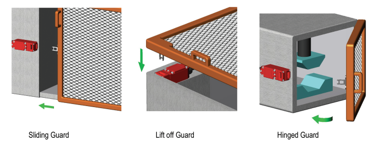
One of the most common types of interlock safety switches, tongue interlock safety switches have tongues or keys that must be physically inserted into the switch housing for normal machine operation to take place. The switch element is typically mounted to the static frame, while the actuator (the tongue/key) is attached to the moving part (see Figure 1). If the tongue is removed from the switch, for example when a door is opened or a cover removed, the safety circuit is broken. This removes the signal from the logic device, triggering the machine to move into a known safe state by slowing or stopping. Only after the tongue/key is reinserted into the switch will the safety circuit permit normal machine function.
Tongue interlock safety switches are well known, easy to install, and economical. On the downside, they’re intolerant to misalignment and can be defeated.
Safety Enabling Switches
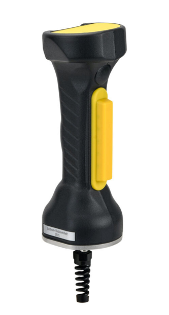
For some applications, routine maintenance tasks like clearing jams or cleaning may require controlled motion while personnel are inside restricted areas. Safety enabling switches are three-position switches (off-on-off) that can signal the SRCR to limit motion or perform other tasks in a controlled manner, only when the switch is held in the central position (see Figure 2). Safety system designers can use safety enabling switches to allow the machine to be jogged or run at slow speed even when doors are open or personnel are within the enclosures using commands like safe direction or safely limited speed. Fully depressing or releasing the switch will result in the machine instantly moving into a safe state.
Sensors
Sensors are valuable tools for increasing safety while reducing the need for guarding. Sensors can be used to detect operator position and send the signal to the logic device, which in turn generates commands to put the machine in a safe state when required.
Safety Light Curtains
Safety light curtains can be used to protect personnel from hazards in areas where barriers are impractical. A light curtain consists of a linear array of photo emitters and a separate array of photodetectors. When a photodetector receives the optical beam, it generates a signal. Breaking the optical beam cuts the signal sent to the logic device, causing it to put the machine in a safe state.
Safety Laser Scanners
Safety laser scanners detect objects via backscatter over a wide angle. Using time-of-flight technology, they can monitor distance, making them useful for zone safety.
Safety Mats
Safety mats are pressure-sensitive devices that offer a variety of implementations. They can be used to detect the presence of personnel in a hazardous area, slowing, then stopping the machine as risk increases. Conversely, they can provide a way to ensure that personnel are in a safe position by preventing operation of the equipment unless the person is standing in a designated spot, such as at the control panel outside of the barrier.
Other options include safety edges and bumpers, which can protect personnel from moving doors and equipment.
Operator-Invoked Stops
Traditional operator-controlled safety sensors include E-stop buttons for proximity control and cable-pull safety switches for stoppage at along a distance.
Bypass-Resistant Safety Devices
Few people would argue with the value of safety systems to protect personnel from injury or worse. That said, safety measures can be perceived as causing line stoppage and reducing throughput. This gives rise to efforts to defeat safety measures, such as fastening a magnet over a sensor or simulating a tongue/key with a bit of metal so that a door or panel can be opened while the machine continues running. “I’ll be quick,” or “I’ll be careful,” a staffer might say but they can’t really guarantee that. Also, once a machine is placed in an unsafe state, there is no protection for any other personnel who might not be aware of the actions of their colleagues. Look for non-defeatable devices designed to prevent bypass. Here are a few examples:
Solenoid Locking Tongue Interlock Safety Switches
These contact safety switches operate similarly to the conventional tongue interlock safety switch – access to the guarded region isn’t allowed until the tongue/key is released from the switch body, which then causes the safety system to slow or stop the machine. The critical difference is that the tongue/key is held in place by the solenoid and can’t be released until the solenoid is energized.
Energizing the solenoid is typically controlled through the PLC or safety relays. This approach ensures that the door can’t just be muscled open and limits access only to qualified personnel. To increase protection levels, it can be equipped with a delay timer to allow machinery to stop before the solenoid is energized to release the switch.
RFID Coded Safety Switches
RFID coding adds a layer of non-defeatability to safety switches. There are different levels of coding dependent on the amount of anti-tampering required. Uniquely coded RFID non-contact switches have some of the best anti-tempering properties.
Two-Hand Safety Controls
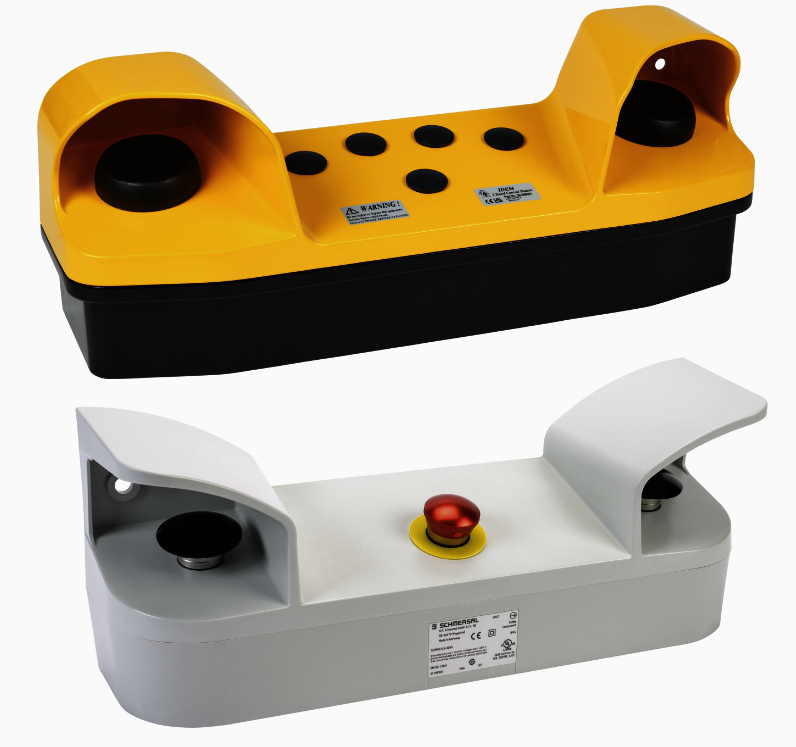
One specialty non-defeatable solution is the two-hand safety control. Designed for equipment with hazardous closing motions like hydraulic presses, these controls require actuation with two hands simultaneously to initiate and complete the operation. The goal is to ensure that the operators’ hands and arms are out of range of moving equipment during the entire stroke.
As with so much else in safety design, the devil is in the details. The two units need guards and sufficient separation to ensure that an operator can’t use the hand and elbow on the same arm to operate the machine (see Figure 3). The logic device, commonly a two hand control relay, should allow only fractional latency between the two signals, to prevent an operator from activating the actuators sequentially with a single hand. Two-hand safety controls should be wired with a control monitoring relay.
Safety Logic Devices
Safety logic devices analyze safety input to detect hazards. If a hazardous situation is identified, the safety logic will command other devices to bring the machine to a known safe state. There are three classes of safety logic devices with increasing levels of functionality, complexity, and, of course, cost: safety relays, configurable safety relays, and safety PLCs. The optimal choice depends on the risk assessment, the requirements of the application, and any project constraints such as budget.
Safety Relays
Standard safety relays are simple, robust, easy to install, and cost-effective. To discuss safety relays, we should first start with the standard electromechanical relay. In these devices, an applied voltage energizes an electromagnet that toggles the position of a contactor, for example from normally closed (NC) to open or from normally open (NO) to closed. In theory, this could be used with a safety device such as an E-stop. In normal function, the electromagnet would keep the safety contact closed to permit machine operation. When an operator hit the E stop, it would cut the voltage signal to the relay, which would open the safety contact and stop the machine. So far so good, right? The problem arises when the relay begins to age, or a voltage surge fuses the contacts. Now, they can no longer respond to the voltage cut off and the machine could continue to run even after the E-stop was pushed.
Enter the safety relay. Safety relays incorporate monitoring logic, circuit protection, and redundancies to ensure reliable operation. They require two inputs so that if one fails, it is detected, and the machine is put into a safe state.
Safety relays are available many versions capable of monitoring one or more devices.
Configurable Safety Relays
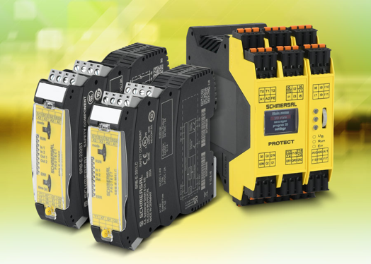
As machine and safety system complexity rises, standard safety relays become unwieldy. In these cases, safety configurable relays can be an excellent solution. They can be used to monitor a variety of devices (see Figure 4). Some units are programmable, while others can be extended with additional safety contacts and signaling outputs.
Safety PLCs
With increased memory and processing power, safety PLCs are ideal for complex machines and, in particular, functional safety. They’re more expensive and require more expertise but the trade-off is flexibility and the ability to expand to meet future needs.
Safety Output
Safety output is a critical part of the safety system. In the simplest form, it can take the form of a standard safety relay causing the safety contact to open, cutting power to the machine. In a more complex design, a safety PLC might send a command to a safety-rated drive to invoke functions such as safely limited speed, safe direction, or safe torque off (followed by application of an external brake, if freewheeling does not satisfy requirements).
Safety systems are essential to machine design and operation. Begin with the risk assessment at the very start of machine development. This will streamline the process, optimize safety, and minimize cost. The risk assessment provides an indispensable tool for the process of designing a safety system with the optimal safety inputs, logic devices, and safety outputs. Don’t forget to take advantage of configurable safety relays as a cost-effective middle ground between standard safety relays and safety PLCs. Most of all, don’t be shy about reaching out to your vendors for guidance. They can help you design the most effective system for your requirements, application, and budget.