Thinking back on my first Computer Programming course, the instructor was adamant about flow charting, documenting, and using good tools to design the program. I was 18 at the time and thought, “Anyone can write a good program and documentation isn’t needed. Write it correctly and it’s done.”
It didn’t take long to see just how naïve I was about those assumptions. Software programming of any sort is rarely static. Customers always want something different — daily production numbers, cast off count, hourly averages, and the list goes on and on. Not to mention that debugging is difficult enough without trying to guess what a function does with no documentation to clarify the logic.

I have debugged many programs over the years, both mine and other people’s work. Some are wonderfully documented and a pleasure to debug. Others are just as wonderful in a completely different way. We have all seen those.
Below are some ideas to help spark your creativity while writing and documenting a PLC program.
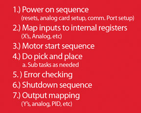
A good place to start is by outlining your code. The outline consists of the major program segments and what will go in them. It is a rough guide of how to lay out any Stages or subroutines as well as calling out the main parts of the program.
Error Checking
Don’t forget to lay out a guide for the error checking section as well as any alarming and shutdowns that need to occur. Error checking is one of the most ignored sections of a program. A good program should be checking switches that go out-of-range for longer than they should, indirect addressing pointers that stray outside their bounds, as well as checking analog signals for validity. There is much more that should go into a good error checking routine, but these examples should help you consider the types of things that you should include.
Memory Map
Design a map for the variable memory. When troubleshooting, it is invaluable to have a guide to the memory layout. Instead of assigning memory registers as you need them with no forethought, try laying out a simple idea of how the memory can work for you. Relate bit addresses to timer addresses and counter addresses to preset addresses. This doesn’t mean they have to be identical, but perhaps C100 goes with T0 and CTA100 goes with V4100. Relating addressing makes troubleshooting go much more smoothly as you can remember the relationship without stopping to look it up.
Tag Names
Most software packages offer the use of tag names. Make your tag names descriptive, such as “Exhaust. Valve101. Unload.bit”. By creating a descriptive name it tells us exactly how the tag is used. “Bit” tells us it is a discrete value on/off. “Unload” tells us that it is unloading whatever the valve is tied to. “Valve101” tells us which part of the valve train we are referring to. “Exhaust” tells us it is part of the exhaust valves.
With a PLC that supports un-typed memory such as the DirectLOGIC line of PLCs, it’s important to note what the memory location contains; such as a unsigned integer, 16 bit BCD word, floating point data, or whatever is in the register. If you use the nickname tag to identify the memory address, when you go to import your PLC program tags into the HMI database you will automatically know which tags need to be changed to a different data type with no confusion, regardless of which data type is in the PLC register.
Code Structure
Before starting the actual coding, ask yourself a few questions to help focus your thoughts on how you will write the code.
1.) Does it make sense?
Sure, I can use indirect addressing and save some coding time, but does it make sense to do so? It may save time now, but how about debugging? How much time will it cost me then? Will the person maintaining the machine understand what I did?
2.) Is this something that I will understand in a year?
The sad answer to this question is often “no”. If it’s difficult to understand now, think of what it will be like when you come back after being away for a while. Take the time to rewrite it into something that anyone can understand. You will be glad later when it is installed and running.
3.) Is saving time or memory space important?
I can write this elegant little chunk of code that takes the place of 100 rungs of ladder. But just because I can, doesn’t always mean I should. If memory space is not limited, the more straightforward approach might be better.
Writing code with an audience in mind is more difficult in the beginning, but it pays off when the plant manager doesn’t call you at 3 a.m. because the machine is down and no one can
understand what you programmed last year.
Documentation
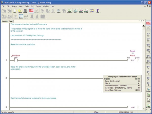
Documentation is important. Program headers should explain what the program does in a broad and general way. This should be at the top of your program. Section headers should explain what each section does; program and hardware setup, input mapping, startup, run, shutdown, alarming, output mapping, etc. Line comments should explain each line that does something unique. Document your constants that you compare against. Thinking “What?”, “Why?”, and “When?” will help with commenting the rungs. (Figure 3)

To sum it all up, you really can’t have too much documentation. However, you have to achieve a balance between time invested and readability. Some documentation is better than none, and documenting the details will make your job easier in the long run.
View products from AutomationDirect that relate to this article: DirectLOGIC PLCs ׀ DirectSOFT PLC Programming Software
By Richard Palmer
AutomationDirect
Originally Published: Sept. 1, 2008


