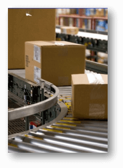
PLCs play a major role when it comes to material or package handling operations. Conveyors, motors, drives, object detection sensors and of course controllers are used quite often when it comes to delivering your suitcase to the right airplane or getting the laptop you ordered to the right delivery truck. But how would you go about coding the PLC for a package handling application? Fortunately, I have firsthand experience with these kinds of systems and I’ll show you one way to go about it.
To track a package as it moves along a conveyor, you first need to let the PLC know when and how far the conveyor is moving. This can be done by mounting a rotary encoder along the conveyor belt. Rotary encoders…well…rotate…and will emit a digital pulse for a set amount of rotation. For example, the TRD-MX1000AD rotary encoder will supply 1,000 pulses for every complete revolution. If one revolution equals 1 ft of travel, then the amount of distance travelled per pulse seen by the controller is .012 inch ((1ft. or 12 inches)/1000 pulses). The ppr or pulses-per-revolution of the encoder will determine how accurate the positioning or tracking can be.
One thing to remember with encoder signals is that the speed of the conveyor belt will determine if high-speed input capability is required. Using the example encoder above, if the conveyor at our facility is run at a speed of 120 ft/m, with 1,000 pulses coming into the PLC every 12 inches, that would be 2,000 pulses per second (trust me it works out 🙂 ). The PLC might not be able to keep up with these encoder pulses during its normal scan time and therefore would require high-speed input functionality to be sure no pulses were missed. Missed pulses mean the tracking will be off, and if it’s off enough, that could mean a diverter missing a suitcase on its way to the plane or crushing the laptop you just ordered.
For our example, we don’t need a high level of accuracy so for simplicity we are going to use an encoder that provides 1 pulse per every inch of travel. We’ll also need a photoeye, so the PLC knows when a box is present at the start of the conveyor line. We’ll be controlling three diverters and for a little extra, we’ll add a selector switch to determine which chute the package should divert to depending on the day of the week. Once we have all that installed and wired up, we are ready to code.
Getting a Handle on Package Handling
When it comes to programming any device, there are many methods and techniques possible. I am going to use ladder logic for this package handling application. I will utilize a shift register, a FIFO queue, a counter, and a few other elements. Oh, and I will be doing all of this with the FREE Do-more Designer PLC software. This software is very powerful, and the convenient simulator will allow me to test
the logic operation and hopefully prove this
actually works.

Above is a diagram of the package handling conveyor system we will be controlling. The photoeye is right up front, so we know when a box is present, and the three diverters are positioned at different locations along the belt. We also have an encoder mounted to the conveyor and our chute selector switch is there as well. The whole conveyor line is approximately 17 feet long. Chute 1 is the outbound chute used during Monday, Wednesday and Friday operations. Chute 3 is used on Tuesdays for inbound processing. Chute 5 is used on Thursdays to feed the international package line. What about Chutes 2 and 4 you ask? Well, let’s just say they are manually controlled and used during peak seasons so we will ignore them.
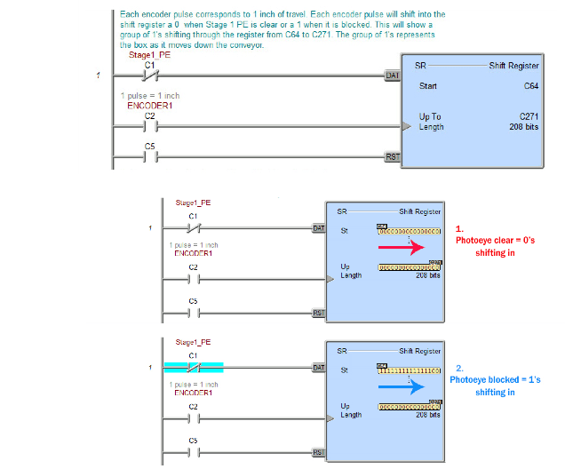
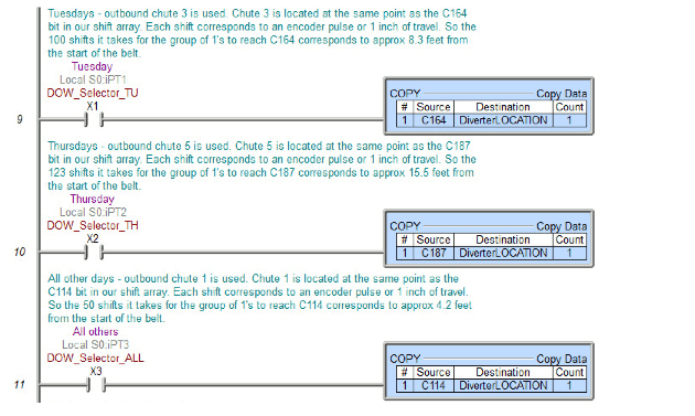
First, in order to track the position of the box(es) on the belt I will use a shift register. As you can see in the code below, I will shift the shift register with every encoder pulse. By making each shift equal one pulse I am essentially making each shift equal one inch of travel. Since I know the location of my diverters in inches from the start of the belt, I know the exact bit in my shift register that corresponds to the diverter location I am looking for. For example, the middle of Chute 3 is 8.333 ft or approximately 100 inches from the start. My shift register starting bit is C64, so the bit I am concerned with for Chute 3 is C164, in other words, it’s C64 + 100 shifts.
The photoeye will determine whether a 1 or a 0 is shifted into the register. When the eye is clear, 0’s will be shifted in and when it’s blocked 1’s will. This creates a group of 1’s, that represent the box, being shifted through the register, which represents the length of the conveyor belt. As soon as the C164 bit has a 1 shifted into it, I know the leading edge of the box has arrived at the middle of Chute 3.
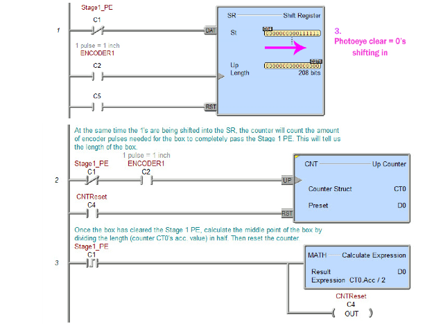
Now when using diverters, it’s important that you do not fire too early on the box since it could be crushed against the side wall or too late since it may just spin and not fall down the chute. You want to aim for the middle of the box. To do that, in the next set of rungs, I’m calculating the middle point of each passing box. The counter in rung 2 will increment the count, while the photoeye is blocked, for each inch the encoder moves. This will count the number of inches needed for the box to completely pass the photoeye or, in other words, it supplies the length of the box in inches.
Once the box clears the photoeye, in rung 3, I then take the length counted and divide it in half to get the middle point. The middle point is stored in D0 and the count is reset for the next box.
Mind your Ps and Queues
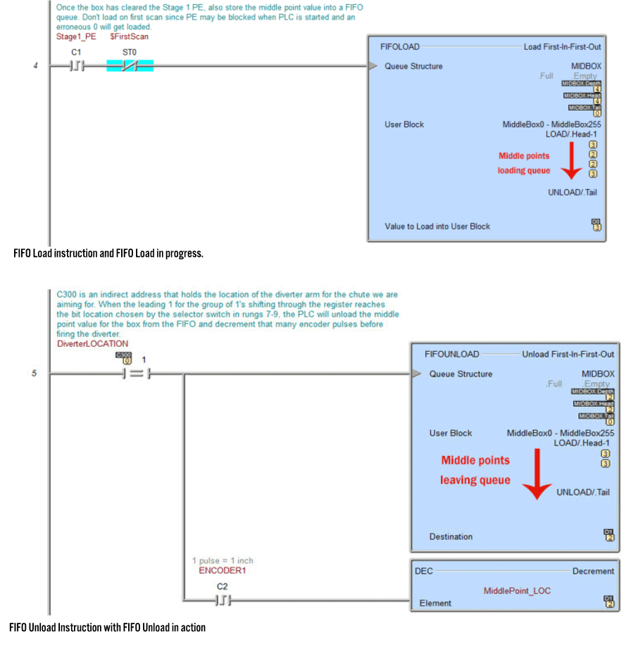
In a normal package handling operation, there are many packages being conveyed and diverted. To keep track of the numerous middle points I could have, and to keep them in sequential order, I queue up these values using the FIFO in rung 4. Once each box clears the photoeye, the middle point for that box is loaded in the FIFO queue. Then the next middle point is loaded and so on. The FIFO queue is set up to hold 255 middle points, which for our facility is more than needed for this conveyor line.
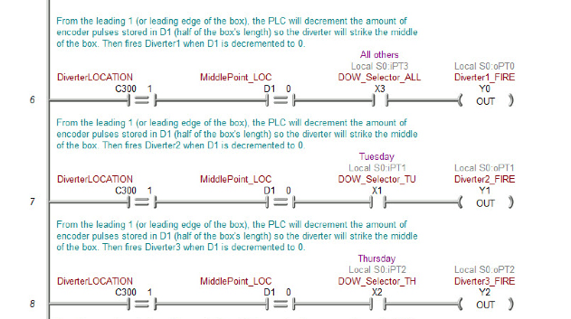
On the other side of the FIFO, rung 5 will unload one value from the queue when the leading edge of a box (represented by the first 1 in the shifted group of 1’s mentioned earlier) has reached the register bit that corresponds to the needed diverter. C300 is being used to hold the value of the bit in the shift register that pertains to the correct diverter location. This is done so the selector switch can change the register bit for the required diverter. As mentioned previously, Chute 3’s bit in the shift register is C164. When the leading 1 in the group of 1’s being shifted finally reaches this bit, the middle point value for that box will be unloaded. That value is then decremented once with each encoder pulse to delay the diverter firing until the box moves the correct number of extra inches along the belt. This will make the diverter arm strike the middle of the box as opposed to the front. Rungs 6,7 and 8 will turn on the output to fire each diverter as selected by the selector switch. To do so, the corresponding shift register bit must see a 1 and the middle point value must have been counted down to 0.
Rungs
9, 10 and 11 will choose the correct shift register bit value to load into C300
depending on what position the selector switch is in. We know C164’s value is
loaded for Chute 3 and we can see in this rung that C114’s value is used for
Chute 1 and C187’s is for Chute 5. Those bit locations in the register
correspond to the 4.2 ft. distance to Chute 1, the 8.3 ft. distance to Chute 3
and the 15.5 ft. distance to Chute 5 from the starting point of
the conveyor.
And that’s it! Each package loaded should be diverted to the appropriate chute. As mentioned previously, there are many ways to go about coding an application such as this. The way I did it here is just one of the ways it can be done. Regardless, as you can see, the shift register and FIFO instructions within the Do-more Designer software made quick work out of coding this. Although I did not discuss it much, the project simulator was also a giant help. If you would like more information on the FREE Do-more Designer software or the Do-more BRX PLC, head on over to www.BRXPLC.com.
Check out the rest of Automation Notebook Issue 42, 2019
All AutomationDirect content and associated training supplies provided in connection there with (the “Materials”), are supplied “as is”. These Materials are provided by our associates to assist others in learning the products we sell and service. We make no representation, warranty or guaranty, whether expressed, implied or statutory, regarding the Materials, including without limitation, implied warranties of merchantability or fitness for a particular purpose. We make no representation, warranty or guaranty that the Materials will be accurate, complete, uninterrupted, error free or non-infringing, or are suitable for your particular application, nor do we assume any responsibility for the use of this information in your application. Copyright © 2021 automationdirect.com