In Part One of this article we discussed the equipment and procedures used to manage the damaging effects of arcs in electrical equipment. In Part Two, we will discuss some of the basic methods, tools, components and circuits that should be used to operate safely around circuits with high arc potential. Part One can be found on our web site at: library.automationdirect.com/electrical-arcs-part-1-of-a-2-part-series-issue-18-2010/
Surge Suppressors
To a very large extent, arc suppression is accomplished by controlling high voltage transients. If a sudden voltage spike initiates a spark within a circuit with access to sufficient energies, an extremely damaging arc may result.
Recently, the application of commercially available surge suppressors has become the accepted method for controlling these transients. In most cases, a large capacity surge suppressor is applied at the primary power connection while lesser units are applied throughout the equipment or distribution system as necessary.
In addition to limiting the initiation of arcs, surge suppressors are nearly mandatory for any equipment that uses microprocessor-based components such as PLCs, digital displays and smart products.
Until recently, the performance of surge suppressors has varied among manufacturers and even from component to component. This held true even though they all carry the same ratings and were, presumably, tested using the same procedures.
This anomaly has been due principally to UL’s 1449 standard which specifies testing procedures for these devices. Previous versions of this standard left more than a few “loopholes” in testing procedures, which allowed manufacturers a little too much latitude in certifying their products.
Over the past two years, UL 1449 has been repeatedly updated to better quantify the testing and make the procedures less ambiguous. The current version provides concise testing and procedural guidelines, leaving very little to interpretation. This should ultimately have the effect of producing a more uniform industry standard.
Crowbar Circuits
Electrically speaking, a “crowbar” is a circuit specifically designed to automatically discharge potentially hazardous voltages from a piece of equipment when it is turned off, if the power is disconnected or if it experiences a fault.
A great deal of electrical equipment uses internal components that have storage potential. Even after the power is disconnected, many electrical components retain lethal electrical energies.  The best example of these components is capacitors. Large capacitors retain a great deal of energy for long periods of time – days, weeks and, in some instances, even months. If an unaware technician comes in contact with these components, he may sustain serious injuries or even be killed.
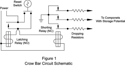
The basic crowbar is a fairly simple circuit and, in the interest of safety, should be kept that way. Figure 1 shows a typical crowbar circuit.
It consists of a holding relay that controls one or more shorting relays; in this case, a single, normally closed, three-pole unit. The shorting relays are configured to discharge any stored energies within the main circuit. In some cases the stored energies may be high enough to require some sort of dump load, as shown in the illustration. These dump loads are typically in the form of a high wattage resistor. Crowbar circuits are commonly designed to automatically reset, but they may also carry a manual reset key. (In this case, the circuit shown contains a manual reset.) Intended to add another level of safety to the equipment, the manual reset assures that the equipment cannot be reenergized without a specific action from a technician.
The Grounding Hook
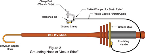
For a variety of reasons, most extremely high voltage equipment can’t realistically utilize crowbar circuits. In these cases the technician must be sure that all components with storage potential are manually discharged and remain in that state during the service work. This is the realm of the grounding hook, as shown in Figure 2.
 These units consist of a copper bar bent with a long-leg hook. The shaft is insulated and the opposite end has two handles with a high voltage hand guard. A plastic-coated piece of aircraft cable is connected to a copper plate and bar. The opposite end of the cable is connected to a bolt-on ground clamp. The bolt-on clamp assures that the ground connection can’t be casually or accidentally disconnected.
Even though a grounding hook is a shorting device, it typically carries a maximum voltage rating. As with any high voltage equipment, never exceed the maximum voltage rating of the unit; doing so may cause serious injury or death. In use, grounding hooks are often permanently mounted in the area where they are to be used. After the equipment is disconnected from the power source, the sticks are hooked onto the appropriate terminals to assure that the circuit is completely discharged and remains in that state.
Live Testing
Despite how much technicians try to avoid it, sometimes it is simply necessary to troubleshoot an energized circuit and/or conduct live testing. In these situations, crowbar circuits and grounding hooks do nothing to protect the technician.
During live testing, arc hazards are at their peak; personnel should exercise great care in these environments. To a large extent, arc suppression during live testing is done by identifying high potential areas and avoiding anything that will deteriorate the stand-off effectiveness of the equipment. If the technician inadvertently inserts a conductive tool between two high potential terminals, it may initiate an arc that can produce serious injury or even death.
Poor grounding exacerbates this condition and only serves to heighten arc hazards. In a situation where an arc forms within a properly grounded cabinet, the hazard is safely contained and does little more than startle the technician. However, if the cabinet isn’t grounded, an inadvertent arc may form through the person standing in front of the box, which can instantly kill them.
Dirt build-up can significantly reduce the stand-off voltage of any electrical component. As stand-off voltage is reduced, arc hazards increase. It is very important to keep high voltage equipment clean. If a piece of equipment is particularly dirty, it should be cleaned or replaced before any live work is conducted. Properly cleaning a piece of hazardous electrical equipment can mean the difference between an uneventful afternoon and one you’ll remember for the rest of your life.
High Voltage Meters and Probes
Troubleshooting high voltage equipment is typically done with specially designed high voltage meters or ordinary multimeters equipped with specialized high voltage probes, as shown in Figure 3. This particular probe is rated at 25 KV and has a 100 to 1 attenuation factor. The meter is set to the 250 volt range and the probe is connected to the input terminals. The technician simply multiplies any reading by 100 to determine the circuit voltage. (Figure 3)
Following a few basic safety procedures makes using these probes very safe. On the other hand, ignoring these procedures can cause serious bodily harm and even death. Remember, when working around this type of circuitry, there is no middle ground.
When using any high voltage instrumentation, always read and understand the manufacturer’s recommendations concerning the specific equipment.
When using high voltage probes, always connect the grounding lug to a suitable earth ground. This connection serves an important safety function as it adds a second level of protection for the technician.
Similarly, never use a high voltage probe at voltages higher than its maximum rating. During operation, one hand should be in your pocket and the other should be used to grip the handle. Never touch the probe in front of the hand guard, even when the probe is not in use. Obviously, touching the forward part of the probe during use greatly increases the technician’s chance of electrocution. Touching the forward part when not in use will deposit oils and dirt from the skin. Over time, contaminates like these can build up and affect the stand-off voltage of the probe.
Have your high voltage probes re-qualified by the factory on a regular basis. Never use a high voltage probe of unknown origin. If the history of the probe is not clear, it should either be sent back to the manufacturer for re-qualification or destroyed. Inspect your high voltage probe before each use. In any high voltage case, work being conducted on this type of circuit should always be carried out by personnel who have been properly trained for the specific equipment and safety issues that apply to the environment. Additionally, a spotter technician, trained in CPR, should always be present when personnel are working with potentially hazardous electrical equipment. With the right equipment, proper training and judicious application of safety procedures, a technician can safely work with and around equipment that would otherwise be considered lethal.
Read Part One of the series here: http://library.automationdirect.com/electrical-arcs-part-1-of-a-2-part-series-issue-18-2010/
By Brian S. Elliott[hozbreak]
Originally Published: Dec 1, 2011


