What is an Encoder?
An encoder (for industrial controls) is a special sensor that captures position information and relays that data to other devices. The position information can be read in many ways (optically, magnetically, capacitively, etc.). There are two basic geometries for encoders: linear and rotary. A linear encoder typically consists of a scale (a coded strip) and a sensing “head” that reads the spacing between the scales’ coding to determine position. A rotary encoder typically consists of an internal coded disc and a sensing head to determine rotary position. A linear encoder is very similar to a tape measure, while a rotary encoder is more like a measuring wheel.
Rotary vs. Linear Encoders
Rotary and linear encoders both define their accuracies in similar ways. A linear encoder’s resolution is measured in pulses per distance (pulses per inch, pulses per mm, etc.). The scale (coded strip) has a set resolution embedded into it or on it that the head reads. Rotary encoder resolution is measured in pulses per revolution (PPR), also known as “line count”. A 2000 PPR encoder has twice the resolution of a 1000 PPR encoder. All the encoders sold by AutomationDirect are rotary encoders.
Optical Encoders
All of the Koyo encoders sold by AutomationDirect are optical rotary encoders. Optical encoders contain a disc within the case with “slots” or “lines” cut into it. The number of slots in the disc varies depending on the resolution of the encoder. A 1000 PPR encoder has 1000 slots cut into the disc. An emitter on one side of the disc emits light through the slots to a receiver on the other. As the slots pass between the emitter and receiver, the receiver alternately detects light and dark; this is how the encoder senses movement and measures position.
Capacitive Encoders
The Modular Kit Encoders (from CUI Devices) sold by AutomationDirect are capacitive encoders intended primarily for use with our stepper motors and to commutate BLDC motors.
A capacitive encoder is comprised of three main components: a rotor, a stationary transmitter, and a stationary receiver. The rotor contains a sinusoidal pattern and, as it rotates, the high-frequency reference signal of the transmitter is modulated in a predictable way. The receiver detects the changes in capacitance-reactance on the receiver board and translates these changes, using a demodulation algorithm, into increments of rotary motion.
Derived from the same principles used in digital calipers, capacitive encoders are highly reliable and accurate. Capacitive encoders are very rugged, tolerating a range of environmental contaminants such as dust, dirt, and oil, as well as vibration and temperature extremes. Further, with no LED, it has a longer lifetime, a smaller footprint, and lower current consumption (6 to 18 mA) than an optical encoder. Immune to magnetic interference and electrical noise, it is as rugged as a magnetic encoder but delivers greater accuracy and higher resolution.
Given their digital nature, capacitive encoders also offer increased flexibility, allowing users to change the encoder’s resolution while a typical optical or magnetic encoder must be swapped out each time a different resolution is needed. The programmable
resolutions available in capacitive encoders are not only useful for system optimization, particularly when designing for PID control loop, but can reduce inventory levels, as one model can be used across multiple applications. Capacitive technology also
allows the ability to digitally set the index pulse and alignment of the encoder for BLDC commutation, while its built-in diagnostic capabilities provide designers access to valuable system data for quick troubleshooting in the field.
Quadrature Encoders
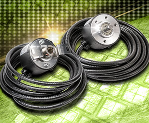
All encoders from AutomationDirect are also quadrature encoders. Quadrature encoders utilize two different sets of “slots” on the optical disc inside the case. These different sets of slots are referred to as channels and are typically called “A” and “B”. The “A” and “B” slots on the encoder disc are offset so that their outputs are out of phase by 90 degrees. This results in 4 different “states” (see a, b, c, and d in the picture below) that the combination of the outputs could be in for any given disc position. This timing diagram comes directly from an insert that ships with an encoder:
Time slice “a”: A = OFF and B = ON
Time slice “b”: A and B both OFF
Time slice “c”: A = On and B = OFF
Time slice “d”: A and B both ON.
(Image 1)
So, a quadrature encoder with a resolution of 100 pulses per revolution would actually produce 400 different states for each revolution of the encoder. That’s why quadrature encoders are sometimes referred to as x4 (times 4) encoders. The pattern of A and B turning ON and OFF also reveals which direction the encoder is turning. Each encoder defines the direction of the quadrature pattern. This encoder has A = ON, then B = ON when rotated in the clockwise direction. If this encoder were to be rotated CCW, B would turn ON first, then A would turn ON.
Z-Pulse Encoders
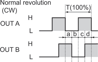
On our incremental encoders, there is another channel called the Index Channel, or Z pulse (“zero position pulse”). This output pulses once per revolution of the encoder. It is used to indicate when the encoder disc crosses the fixed zero position inside the encoder. The Z-pulse can be used to reset a counter or can be used for very precise homing. Our SureServo servo drive uses an incremental encoder as a feedback device and has a homing mode where the motor is homed to an external signal (a proximity switch, mechanical limit switch, etc.), then the motor proceeds to the next occurrence of the encoder’s Z-pulse. This results in extremely accurate positioning. The Z-pulse for Koyo optical encoders is factory set and cannot be moved, while the position of the Z-pulse for the modular CUI encoders is adjustable via a USB cable and our free configuration software. Several families of our optical encoders also offer “servo mounting clamps” that allow the body of the encoder to be rotated, or “clocked”, after installation so that the Z-pulse signal occurs in the desired position relative to a machine function. The KM-9D kit provides a servo mount clamp for the TRD-GK encoders; the NM-9D and the NF-55D kits clamp the TRD-N, TRD-NH, and TRD-NA families. (Image 2) Image 2 shows a complete timing diagram for a 5 PPR encoder. Notice that the Z pulse stays on for one entire cycle of output B.
Incremental vs. Absolute Encoders
Encoders come in incremental and absolute styles. An incremental encoder only reads pulses, and when it powers up, it has no information about location; it can only tell you how far it has moved since being powered up. Think of an incremental encoder as a tape measure with no numbers on it, only tick marks: you can tell how far you’ve moved, but you don’t know exactly where you are unless you measure from a known spot. In contrast, a single turn, rotary, absolute encoder can report back exactly what angle it is at even at power up. Think of an absolute encoder as a compass: you know exactly what position the compass is in when you first look at it. One drawback of single-turn absolute encoders: you know the exact angle the encoder is sitting at when powered up, but you do not know how many turns were made before power was applied. To solve that problem, there are also multi-turn absolute encoders. These encoders usually have a battery or super-capacitor that monitors how many revolutions the encoder has turned even while power is off. Think of a multi-turn absolute encoder as a measuring wheel which increments once per revolution. Multi-turn absolute encoders typically have serial communication and require special receivers to decode their position information.
Our Koyo absolute encoders are single turn encoders. They have a special disc inside that has several channels’ worth of information on it. Our encoder with the least resolution has 5 physical outputs (5 bits’ worth of data). The TRD-NA32NWD encoder has 2^5 = 2*2*2*2*2 =32 unique positions per revolution (absolute encoders still use PPR). This 5-bit encoder requires 5 digital inputs to a PLC, etc. Currently, our highest resolution absolute encoder, TRD-NA1024NWD, has 10 bits of resolution, or 2^10 = 2*2*2*2*2*2*2*2*2*2 = 1024 pulses per revolution. The 10-bit encoder requires 10 digital inputs to a PLC.
In general, incremental encoders must be wired into high-speed inputs (although our 3 PPR encoder (TRD-N3-RZWD) would not necessarily produce a high-speed pulse train). Absolute encoders, however, are designed to be wired to general-purpose I/O. So the 10-bit absolute encoder described will wire into 10 general-purpose PLC inputs.
Gray Code
There is one more special consideration for our single-turn absolute encoders: they don’t count in standard binary. Here is the way binary normally counts up:
Decimal # Binary code
12 01100
13 01101
14 01110
15 01111
16 10000
17 10001
18 10010
Notice the transition from Decimal 15 to 16: all 5 digits change state at once. In the real world, this could cause serious problems. If the PLC is reading inputs when this transition occurs, a bad value could temporarily be decoded by the PLC (at least for one scan). When outputs on a machine are turned on and off based on encoder position, you can see that this could be a big problem. This may not happen very often, but considering the PLC updates its input image table every scan (hundreds, if not thousands of times per second), any glitch in reading position could be disastrous. To combat this problem of reading multiple transitions, Gray Code was developed. Gray Code is a special kind of binary that only increments one bit at a time. Since only one bit changes each transition, a PLC will not decode erroneous position data. The only drawback to Gray Code is that it is not very intuitive when watching the bits change state.
Decimal # Binary Code Gray Code
0 0000 0000
1 0001 0001
2 0010 0011
3 0011 0010
4 0100 0110
5 0101 0111
6 0110 0101
7 0111 0100
However, the logic to decode gray code is very straightforward and can be done with minimal ladder programming. Our Productivity3000, Do-More, and some DirectLOGIC PLCs actually have pre-configured instructions that automatically decode the Gray Code digital inputs into decimal values. For more details on Gray Code, universal ladder logic decoding examples, and special Gray Code PLC instructions, see this Technical Note on our Support homepage:
https://support.automationdirect.com/docs/absolute_encoders.pdf
Electrical Outputs
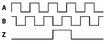
Our encoders come with one of several different kinds of electrical outputs: Line Driver, NPN Open Collector, or Push-Pull (Totem Pole). A line driver output is a differential signal and requires two unique output wires per channel. Typical wire designations are A, A- (A “not”), B, B- (B “not”). When channel A is ON, there is a positive voltage between A and A-. When channel A is OFF, there is a negative voltage differential between A and A-. The magnitude of the voltage differential will be greater than 2.5V. The same happens for the B and Z channels. Line Driver encoders allow very straightforward wiring to compatible PLC or motion controller inputs. Each output (A, B, Z) requires two wires, plus two wires for the power supply (usually 5VDC). (Image 3)
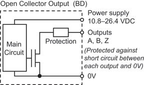
A second output type is an open collector. NPN open collector encoders “sink” current from sourcing (PNP) PLC inputs, and require only one wire per channel, plus one 0V (DC common) wire for all the current return. An open collector encoder would have A, B, Z, and 0V wires (and a wire for +DC to power the electronics). NPN Open Collector (sinking) encoders require the master PLC or motion controller to have PNP (sourcing) inputs. Open collector encoders usually accept a wide range of voltage. AutomationDirect offers models with ranges of 5–12VDC, 12-24VDC, and 5-30VDC. (Image 4)
The third type of encoder output is a Push-Pull circuit, also known as a Totem Pole output. The Push-Pull output is a special circuit that can sink OR source current to the PLC. The key to this encoder’s circuit is the pair of transistors in the encoder. When one transistor is ON, the other is OFF. If the PLC supplies current (i.e. has sourcing or PNP, inputs), the Push-Pull encoder can sink current through the lower transistor. If the PLC sinks current (i.e. has sinking or NPN inputs), the encoder will source current through the upper transistor. The circuitry looks similar to a totem pole, hence the alternate name. (Image 5)
Light, Medium vs. Heavy Duty
One of the first ways AutomationDirect differentiates encoders is by duty: we have Light Duty, Medium Duty, and Heavy Duty encoders. The key difference is how much load may be applied to the shaft. Our smallest encoder, the TRD-MX (4mm shaft), can only handle 10N (2.25 lbf) radial force on the shaft. In contrast, our heavy-duty encoders, the TRD-GK (10mm shaft), can handle 100N (22.5 lbf) of radial force on the shaft.
Environmental ratings also become more robust as the Duty increases. Our Light Duty encoders are IP40 and IP50 (dustproof). The Medium Duty and Heavy Duty encoders go as high as IP65 (splash-proof). This selection guide details the most significant differences between the Koyo encoders offered by AutomationDirect. Note that all the encoders come with a 2m cable except for the TRDA-25 encoders, which come with a military-style connector. AutomationDirect also carries mating connectors and pre-made mating cables for the TRDA-25s.
A selection guide is located under the “Technical Information” tab on any AutomationDirect encoder Web page. https://www.automationdirect.com/static/specs/encoderselect.pdf
(Image 6)
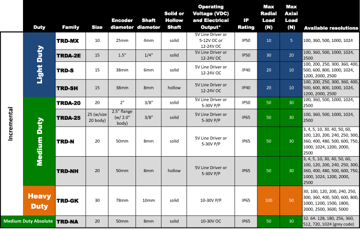
All our encoders feature an integral 2m cable except for the TRDA-25 series which has an MS connector
*Operating Voltage and Electrical Output:
• LD = Line Driver (all Line Drivers require 5VDC supply)
• OC = NPN Open Collector (at Operating Voltage)
• P/P = Push Pull or Totem Pole (at Operating Voltage)
Speed Limitations
There are two limitations on speed when it comes to rotary encoders: mechanical and electrical. The mechanical speed limit is a fixed RPM value for each family which is the maximum speed those encoders can withstand without breaking. There is also an electrical speed limit for each family of encoders which is imposed by the switching speed (frequency response) of the electronics inside the encoder. The switching speed for an encoder’s electronics is calculated by how fast the encoder is spinning, and the encoder’s resolution. (A 3 PPR encoder spinning at 5000 RPM only produces pulses at 250Hz, while a 1000 PPR encoder spinning at 5000 RPM produces pulses at 83 kHz.) The electrical speed limit is determined by the formula: Max Electrical Speed = (Max Freq Response / pulses per revolution) x 60sec/min
The Maximum Frequency Response is a fixed number (in Hertz) for each encoder family. This is how fast the electronics can switch from OFF to ON. So, each encoder resolution inside that family has a different Maximum Electrical Speed. For example, TRDA-25 encoders have a Maximum Mechanical Speed of 3000 RPM. The Maximum Frequency Response (electrical speed) of the Push-Pull models is 100 kHz.
So, the fastest speed that a 100 PPR TRDA-25 encoder can spin due to the speed of the electronics is (100kHz/100 PPR) x 60s/min = 60,000 RPM (much higher than the mechanical limit of 3,000 RPM). The fastest speed that a 2500 PPR TRDA-25 encoder can spin due to the speed of the electronics is (100kHz/2500 PPR) x 60s/min = 2,400RPM (lower than the mechanical limit of 3,000RPM).
So, if an application requires high speed or high resolution, both the mechanical and electrical speed limits of the encoder need to be considered.
While the above information is mostly geared toward incremental encoders, the same calculations hold true for absolute encoders. One extra consideration for absolute encoders is that general-purpose DC inputs are not high-speed inputs. The OFF-to-ON and ON-to-OFF response times of general-purpose DC input cards may limit an absolute encoder’s speed more than the encoder’s switching frequency.
Other Notes
Some other characteristics of encoders offered at AutomationDirect:
- TRD series encoders have metric dimensions.
- TRDA series encoders have SAE (inch) dimensions.
- Encoder part numbers with a “V” in the suffix are Line Driver models.
- All Koyo encoders come with an integrated 2m cable except the TRDA-25 encoders: they have an MS connector (separate mating cables and connectors are available).
- Shaft couplings are available for all encoder families: metric-to-metric, inch-to-inch, and metric-to-inch.
- Right angle mounting brackets and various round and square flanges are also available
By Joe Kimbrell
Product Manager, Motion Products
Originally Posted: March 1, 2013. Reviewed/updated Jan 22, 2021